Propeller governing mode:
The speed lever is placed in the high position. The engine is operating at 97 percent. As the power lever is advanced ahead of the flight idle detent this causes the power lever cams to react by momentarily holding a fixed pitch and increasing fuel. As RPM increases, it reaches overrides the underspeed governor and reaches the propeller governor setting of 100 percent. The propeller governor then takes control of blade angle and increases it to maintain the selected RPM by equalling load with the power demand. This is known as 'propeller governing mode' of operation. Because of the cut of the cam the propeller pitch control has no effect so the propeller governor has automatic load control. The underspeed governor is effectively overridden by the manual fuel valve.
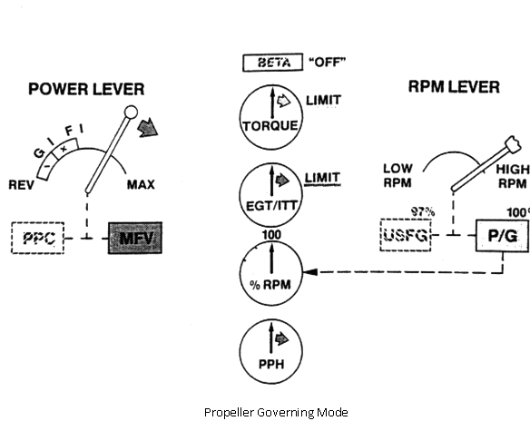
In the prop governing or inflight mode, the range of operation of the power lever is from flight idle to maximum. The effective component is the manual valve. Normal propeller governing mode quadrant of operation for the speed lever is from cruise to takeoff, or high. As previously stated the increased fuel demand drives RPM to the setting of the propeller governor which changes the blade angle of the propeller to equal the demanded power.
To sumarise, during flight the manual fuel valve is the effective component giving a manual power demand. The propeller governor, the other effective component, is responsible for automatic load control to equal with the manual power demand and maintain the selected engine RPM. This is known as 'propeller governing mode'.
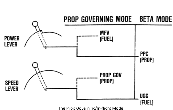
For ground operation, the propeller pitch control provides manual load control, the underspeed governor automatically controls fuel flow in response to load changes. This equals power and load to maintain selected engine RPM. This is called 'beta mode'.
The propeller control system is designed to operate in either of two modes. These modes are; the propeller governing or flight mode and beta or grounding operating mode. In the propeller governing mode, the propeller governor meters oil to the propeller as a function of engine speed, power requirements, and pilot demands through the power lever. In the beta or ground operating mode, oil is metered to the propeller by the propeller pitch control, and the propeller blade angle is controlled directly by the power lever movement.
A pressure switch in the propeller hydraulic control system is used to power an indicator light on the cockpit instrument panel. The light is illuminated when the propeller is operating in beta mode and out when the propeller is operating in governing mode.
If the engine should lose power during flight, a negative torque sensing system is used to automatically effect movement of the propeller blades toward the feather position.