Production of rotating fields from single-phase windings, Electrical Engineering

Assignment Help:

Production of Rotating Fields from Single-Phase Windings

In this subsection we show that a single-phase winding carrying alternating current produces a stationary pulsating flux that can be represented by two counterrotating fluxes of constant and equal magnitude.

Let us consider a single-phase winding, as shown in Figure(a), carrying alternating current i = I cos ωt . This winding will produce a flux-density distribution whose axis is fixed along the axis of the winding and that pulsates sinusoidally in magnitude. The flux density along the coil axis is proportional to the current and is given by Bm cos ωt , where Bm is the peak flux density along the coil axis.

Let the winding be on the stator of a rotating machine with uniform air gap, and let the flux density be distributed sinusoidally around the air gap. Then the instantaneous flux density at any position θ from the coil axis can be expressed as

2358_Production of Rotating Fields from Single-Phase Windings.png

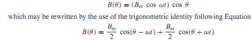
The sinusoidal flux-density distribution given by Equation can be represented by a vector Bm cos ωt of pulsating magnitude on the axis of the coil, as shown in Figure. Alternatively, as suggested by Equation, this stationary pulsating flux-density vector can be represented by two counterrotating vectors of constant magnitude Bm/2, as shown in Figure. While Equation represents a standing space wave varying sinusoidally with time, Equation represents the two rotating components of constant and equalmagnitude,

rotating in opposite directions at the same angular velocity given by dθ/dt = ω. The vertical components of the two rotating vectors in Figure always cancel, and the horizontal components always yield a sum equal to Bm cos ωt , the instantaneous value of the pulsating vector.


Related Discussions:- Production of rotating fields from single-phase windings

What is the difference between a tem mode and a te mode, Q. (a) What is the...

Q. (a) What is the difference between a TEM mode and a TE mode? (b) Explain the terms "cutoff wavelength" and "dominant mode" as applied to waveguides. Find the cutoff wavelengt

Factors affecting frequency response of an amplifier, Q. What is their rela...

Q. What is their relation with gain? What are the factors affecting frequency response of an amplifier? Some amplifiers should be "flat" across a band of frequencies. In other

Define sigma-delta analog to digital converters, Define Sigma-Delta Analog ...

Define Sigma-Delta Analog to Digital Converters? Sigma-Delta ADCs have the benefit of being implemented almost totally in the digital domain.  They are extremely reliable, high

Find the current by means of mesh-current analysis, For the network shown i...

For the network shown in Figure, find the current delivered by the 10-V source and the voltage across the 3- resistor by means of mesh-current analysis.

Mode 1 - buck converter , Mode 1 ( 0 By  applying a positive  output ...

Mode 1 ( 0 By  applying a positive  output  pulse  of the pulse  width modulator to  the  transistor Q 1 it gets turned on.  An input  current  in flows  through V in   Q 1

Determine the rated stator current, A three-phase, wye-connected, 2300-V, f...

A three-phase, wye-connected, 2300-V, four pole, 1000-kVA, 60-Hz synchronous machine has a synchronous reactanceXs = 5, a field resistance Rf = 10, and an approximately linear ma

Explain the asynchronous up-down counters, Explain the Asynchronous Up-Down...

Explain the Asynchronous Up-Down Counters? In some applications a counter must be able to count both down and up and the circuit below is a 3-bit up-down counter. It counts do

Explain the working principle of an opto coupler, Q. Explain the working pr...

Q. Explain the working principle of an opto coupler? When it is necessary to block the voltage between one electronic circuit and another, and transfer the signal at the same t

Determine the current and voltage in given network, Q. For a part of the ne...

Q. For a part of the network shown in Figure, given that i 1 = 4A; i 3 (t) = 5e -t , and i 4 (t) = 10 cos 2t, find v 1 , v 2 , v 3 , v 4 , i 2 , and i 5 .

Write Your Message!

Captcha
Free Assignment Quote

Assured A++ Grade

Get guaranteed satisfaction & time on delivery in every assignment order you paid with us! We ensure premium quality solution document along with free turntin report!

All rights reserved! Copyrights ©2019-2020 ExpertsMind IT Educational Pvt Ltd