Problems on cantilever truss, Mechanical Engineering

Assignment Help:

Problems on Cantilever Truss:

In the case of cantilever trusses, it is not required to determine the support reactions. The forces in members of cantilever truss are obtained by begning the calculations from free end of cantilever.

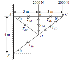
Q Determine forces in all the member of cantilever truss shown in the figure given below 


1370_Problems on Cantilever Truss.png

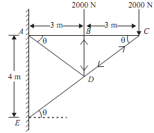
Sol.: From ?ACE, we have

tan θ = AE/AC = 4/6 = 0.66                                                                             ...(i)

Also,                                      1027_Problems on Cantilever Truss1.png

cos θ = AC/EC = 6/7.21 = 0.8321     ... (iii)

sin θ = AE/CE = 4/7.21 = 0.5548 


543_Problems on Cantilever Truss2.png

Joint C:

Consider free body diagram of joint C as shown in the given figure;


1746_Problems on Cantilever Truss3.png

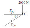
As the three forces are acting, so apply lami's theorem at the joint C.

TBC/sin(90 - θ) = TCD/sin270 = 2000/sin θ

TBC/cos θ = TCD/sin 270 = 2000/sin θ

TBC = 2000/tan θ = 2000/0.66 = 3000.3N         ...(v)
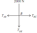
Joint B:


2358_Problems on Cantilever Truss4.png

TBC = 3000.3N (Tensile)                                          .......ANS

TCD = - 2000/sin θ = 2000/0.55 = 3604.9N      ...(vi)

TCD = 3604.9N (Compressive)                              .......ANS

Consider free body diagram of joint B as shown in the given figure

As,                           TBC = 3000.3N

Let,                          TAB = Force in the member AB

TDB  = Force in member DB

As the four forces are acting at the joint B, So apply resolution of forces at joint B

RH = TAB  - TBC  = 0, TAB  = TBC = 3000.03 = TAB

TAB = 3000.03                                                            ...(vii)

TAB = 3000.03N (Tensile)                                       .......ANS

RV = - TDB  - 2000 = 0

TDB = -2000N                                                             ...(viii)

TDB = 2000N (compressive)                                   .......ANS

Joint D:

Consider free body diagram of joint D as shown in figure given below
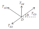
 

1248_Problems on Cantilever Truss5.png

As,                           TDB = - 2000N

TCD = 3604.9N

Let, TA = Force in member AD

TDE  = Force in member DE

As the four forces are acting at the joint D, So apply resolution of forces at

217_Problems on Cantilever Truss6.png


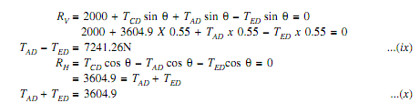
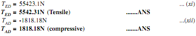
By solving equation (ix) and (x),

2402_Problems on Cantilever Truss7.png


Member

AB

BC

CD

DE

DB

AD

Force in N

3000.03

3000.03

3604.9

5542.31

2000

1818.18

Nature

C = Compression

T = Tension


T


T


C


T


C


C


Related Discussions:- Problems on cantilever truss

What is shatter test, Q. What is Shatter test? Shatter test: This tes...

Q. What is Shatter test? Shatter test: This test is measure of toughness of the moulding sand. It indicates the capacity of the moulding sand to with stand rough handling dur

Schedule selection-generation of continuation, Schedule Selection Of th...

Schedule Selection Of the p excellent continuations, q (first) operations are scheduled. This offers p latest partial schedules. After that step 1 is repeated. These steps'

Principal design criterion of plant layout, Q. Principal design criterion o...

Q. Principal design criterion of Plant layout? Safety-in-Design is a key factor associated with the layout design of any facility. The principal design criterion is to minimize

Steps of centrifugal filter and screen filter cleaning, Centrifugal Filter ...

Centrifugal Filter and Screen Filter Cleaning :   Oil may contain impurities. Since the oil passes through all the engine parts, the impurities may harm the parts and cause imprope

Calculate the Induction Motor Efficiency, A three phase squirrel cage induc...

A three phase squirrel cage induction motor has the nameplate data shown in Table I below  Table I : Induction Motor Nameplate Data. a)  Calculate the induction motor ef

Compute the deflection and maximum bending stress, For the beam shown in Fi...

For the beam shown in Figure compute the deflection at the element nodes. The modulus of elasticity is psi and the cross section is as shown in the figure. Also compute the maximum

Piston leaves the bottom stops , Consider the frictionless piston-cylinder ...

Consider the frictionless piston-cylinder set-up with a linear spring as is shown below. The cylinder has an internal cross-sectional area of AC = 0.1 m2. Distances  y 1 and  y 4

Design loading - unloading facilities in plant layout, Q. Design Loading - ...

Q. Design Loading - Unloading Facilities in plant layout? Loading and unloading areas should be separated. These facilities should be situated on the edge of the site near road

Write Your Message!

Captcha
Free Assignment Quote

Assured A++ Grade

Get guaranteed satisfaction & time on delivery in every assignment order you paid with us! We ensure premium quality solution document along with free turntin report!

All rights reserved! Copyrights ©2019-2020 ExpertsMind IT Educational Pvt Ltd