Principle of three-phase synchronous machines, Electrical Engineering

Assignment Help:

Q. Principle of Three-phase synchronous machines?

In fact, with very few exceptions, three-phase synchronous machines are most commonly used for power generation. In general, three-phase ac power systems, including power generation, transmission, and usage, have grown most popular because of their economic advantages. An elementary three-phase, two-pole synchronous machine with one coil per phase (chosen for simplicity) is shown in Figure (a). The coils are displaced by 120 electrical degrees from each other in space so that the three-phase voltages of positive phase sequence a-b-c, displaced by 120 electrical degrees from each other in time, could be produced. Figure (b) shows an elementary three-phase, four-pole synchronous machine with one slot per pole per phase. It has 12 coil sides or six coils in all. Two coils belong to each phase, which may be connected in series in either wye or delta, as shown in Figures (c) and (d). Equation can be applied to give the rms voltage per phase when N is treated as the total series turns per phase.

1428_Three-phase synchronous machines1.png

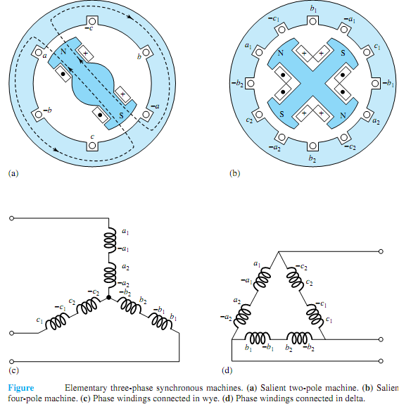
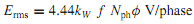
The coils may also be connected in parallel to increase the current rating of the machine. In actual ac machine windings, instead of concentrated full-pitch windings, distributed fractional- pitch armature windings are commonly used to make better use of iron and copper and to make waveforms of the generated voltage (in time) and the armaturemmf (in space) as nearly sinusoidal as possible. That is to say, the armature coils of each phase are distributed in a number of slots, and the coil span may be shorter than a full pitch. In such cases, Equation is modified to be where kW is a winding factor (less than unity, usually about 0.85 to 0.95), and Nph is the number of series turns per phase.

217_Three-phase synchronous machines.png

Special mechanical arrangements must be provided when making electrical connections to the rotatingmember. Such connections are usuallymade through carbon brushes bearing on either a slip ring or a commutator, mounted on-but insulated from-the rotor shaft and rotating with the rotor. A slip ring is a continuous ring, usually made of brass, to which only one electrical connection is made. For example, two slip rings are used to supply direct current to the field winding on the rotor of a synchronousmachine. A commutator, on the other hand, is amechanical switch consisting of a cylinder formed of hard-drawn copper segments separated and insulated from each other by mica.


Related Discussions:- Principle of three-phase synchronous machines

Common-base configuration, Common-base configuration:  The common-bas...

Common-base configuration:  The common-base that is abbreviated as CB transistor configuration, which is as well termed as the 'grounded base' configuration, is displayed in

Magnetism, What is mgnomotive force

What is mgnomotive force

Find the per-phase impedance of the load, Q. The two-wattmeter method for m...

Q. The two-wattmeter method for measuring three-phase power is applied on a balanced wye-connected load, and the readings are given by W C = 836W and W A = 224 W If the system

Emi, #quest explain cro..

#quest explain cro..

Torque required to turn a self excited generator, Work must be done against...

Work must be done against the electromagnetic torque in order to generate the voltage (and current) supplied to the electrical load connected to the generator. Therefore energy con

Single-axis autopilot control system of an aircraft, Q. Single-axis autopil...

Q. Single-axis autopilot control system of an aircraft? Figure (a) shows the block diagram of a simplified single-axis (pitch, yaw, or roll) autopilot control systemwith digita

find the current and voltage by ohms law and kvl, 1. A current carrying co...

1. A current carrying conductor is found to carry 10 μA at a given time slot from 5μs to 1.5 ms. Find the total number of electrons flowing in the conductor during this time slot.

Compute the current loss in the lines, Q. Consider a 240-V supply feeding a...

Q. Consider a 240-V supply feeding a resistive load of 10 kW through wires having a total resistance of R = 0.02 . For the same load, let a 120-V supply be used with a total wire

When both mt2 and gate are negative, When both MT 2 and Gate  are Negativ...

When both MT 2 and Gate  are Negative In this case N 3   works as a remote gate. Current  flows form layer P 2 to layer  N 3 junction N 1 P 1 is reverse biased  and it  br

Write Your Message!

Captcha
Free Assignment Quote

Assured A++ Grade

Get guaranteed satisfaction & time on delivery in every assignment order you paid with us! We ensure premium quality solution document along with free turntin report!

All rights reserved! Copyrights ©2019-2020 ExpertsMind IT Educational Pvt Ltd