Plot velocity and pressure distributions reynolds numbers, Mechanical Engineering

Assignment Help:

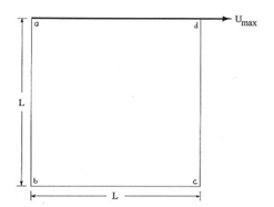
The figure shows a "square cavity flow". In this flow the cavity is filled with a fluid and the lid of the cavity moves with a constant velocity, while the other walls remain stationary. This causes a recirculation within the cavity. The flow is assumed 2 dimensional incompressible, with Umax=1.0 m/s constant. The lengths of the sides of the cavity, L, are all equal to 1.0 m

848_mechanical engineering.png

Run the program for the following Reynolds numbers: 10, 100, 500 and 1000.

The Reynolds number is defined by Re = Umax.L/n, where n is the fluid kinematic viscosity, which in this case, varies to produce the different

Reynolds numbers.

The boundary conditions are:

uab = ubc = ucd = vab= vbc= vcd = vad = 0 and uad = Umax

Use a staggered grid of at least 15x15 cells, and the SIMPLE algorithm for your solutions.

Plot both velocity and pressure distributions for all Reynolds numbers. Please submit your complete solution on either paper or electronically. If you choose paper, you must also send me the computer code electronically.


Related Discussions:- Plot velocity and pressure distributions reynolds numbers

What is a cotter joint, These parts of joints are used to connect two rods,...

These parts of joints are used to connect two rods, which are under compressive or tensile stress. The ends of the rods are in the manner of a socket and shaft that fit together an

Equilibrium of body on the rough inclined plane, Equilibrium of body on the...

Equilibrium of body on the rough inclined plane: If the inclination is less than angle of friction, the body remains in equilibrium without any external force. If body is to b

Computer added design, Computer added design Using SolidWorks create an...

Computer added design Using SolidWorks create an assembly model of the roller, bracket and base shown to the right. The assembly is also shown in exploded view below. You may c

Indicator diagram and indicated power - thermodynamics, Indicator diagram a...

Indicator diagram and indicated power: An indicated diagram is graph between pressure and volume. The former being taken on the vertical axis and latter on the horizontal axis

Explain side cutting edge angle, Explain Side Cutting Edge Angle It is ...

Explain Side Cutting Edge Angle It is angle between the side cutting edge and the longitudinal axis of the tool. It avoids formation of build up edge, controls the direction of

Business Management techniques, how do I Create appropriate costing systems...

how do I Create appropriate costing systems and techniques for specific engineering business functions.

Scope of wps and pqr, Scope of WPS and PQR A Welding Procedure Specific...

Scope of WPS and PQR A Welding Procedure Specification (WPS) is written qualified welding procedure prepared to provide direction for making production welds to code requiremen

Bucket conveyors, Bucket conveyors are used to moves the granular powde...

Bucket conveyors are used to moves the granular powdered or liquid materials. The buckets may be mounted on a chain or a belt. The movement may be vertical or flat. The ver

Write Your Message!

Captcha
Free Assignment Quote

Assured A++ Grade

Get guaranteed satisfaction & time on delivery in every assignment order you paid with us! We ensure premium quality solution document along with free turntin report!

All rights reserved! Copyrights ©2019-2020 ExpertsMind IT Educational Pvt Ltd