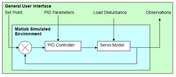
The scope of work is to investigate and report PID tuning methods and to confirm their suitability for 2nd and 3rd Order Servo Mechanisms on a simulated system model utilising Matlab and Simulink.
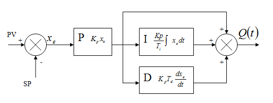
For the purpose of testing, the Ideal (Non-Interacting) PID Controller algorithm shall be used to explore the different tuning methods.
The proposed tuning methods are;
1. Z-N Open Loop & Closed Loop tuning
2. Auto-tuning method (eg. Frequency Response or Relay)
3. Optimised tuning method.
The PID parameters are to be fed into the PID Controller Transfer Function and the effects to the Servo model observed.
Scope of Work
1. Provide a good summary and analysis of the methods relevant to Matlab/ Simulink toolboxes which will be deployed to carry out the tuning testing.
2. Propose a rugged 2nd Order and 3rd Order Servomechanism model to apply the PID tuning methods. The models shall be a challenge and adequately test the proposed tuning methods.
3. Provide a realistic specification of the Servomechanism parameters on which the model is based. Eg. Rotork Motor operated Valve, Moog Servo Valve etc.
4. Propose a realistic disturbance eg. Additional load/ torque. There should be an ability to introduce a "Disturbance" that would test tuned parameters to see how robust the PID Controller is and how accurate/ faithful the tuned parameters were. Explain your reasons.
5. Describe how you will address and deploy the tuning parameters for ZN, Auto-tuning and Optimised tuning methods. This section should make it clear what you will exactly do to implement the data in the PID controller into Matlab.
6. Describe how the observed step responses shall be analysed.
7. Provide a dummy test run example and code used in Matlab and Simulink.