Numerical problems based on the cantilever beam, Mechanical Engineering

Assignment Help:

Numerical Problems Based on the Cantilever Beam:

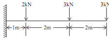
Draw the SF and BM diagram for the beam as shown in the figure given below. Also indicate principal values on diagrams.


715_Numerical Problems Based on the Cantilever Beam.png

Sol.: Let reaction at the support A be RAV, RAH  and M(counter clock wise), First find support reaction

For that,

ΣV = 0

RAV  -2 -3 -3 = 0, RAV  = 8                                                                                             ...(1)

Taking moment about A,

ΣMA  = 0

-M + 2 X 1 + 3 X 3 + 3 X 5 = 0

M = 26KNm                                                                                                 ...(2)

ΣH = 0

RAH = 0

2301_Numerical Problems Based on the Cantilever Beam1.png

Calculation for Shear force Diagram

Draw section line, here total 3 section line, which break the

load RAV  and 2KN(in between A and B),

2KN and 3KN(Between B and C),

3KN and 3KN (Between C and D). Take left portion of the beam
Take section 1-1

Force on left of section 1-1 is RAV

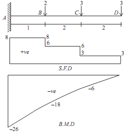
SF1-1 = 8KN (constant value)

Constant value means that the value of shear force at both the nearest point of the section is equal that is

SFA = SFB  = 8KN                                                                                                                        ...(4)

Take section 2-2

Forces on the left of section 2-2 is RAV  and 2KN

SF2-2 = 8 - 2 = 6KN (constant value)

Constant value means that the value of shear force at both the nearest point of the section is equal that is

SFB = SFC  = 6KN                                                                                                                        ...(5)

Take section 3-3

Forces on the left of section 3-3 is RA, 2KN, 3KN

SF3-3 = 8 - 2 - 3 = 3KN (having constant value)

Constant value means that the value of shear force at both the nearest point of the section is equal that is

SFC = SFD  = 3KN                                                                                                                        ...(6)

Calculation for Bending moment Diagram

Assume

Distance of section 1-1 from A is X1

Distance of section 2-2 from A is X2

Distance of section 3-3 from A is X3

Take section 1-1, taking moment about the section 1-1
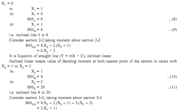
BM1-1 = 8.X1

It is Equation of straight line (Y = mX + C), inclined linear.

Inclined linear means that the value of bending moment at both the nearest point of section is varies with

914_Numerical Problems Based on the Cantilever Beam2.png

It is Equation of the straight line (Y = mX + C), inclined linear.

Inclined linear means that the value of bending moment at both the nearest point of section varies with

2195_Numerical Problems Based on the Cantilever Beam3.png 

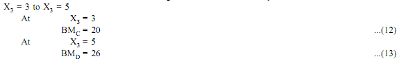
That is inclined line 20 to 26

Plot the BMD  with the help of obtained bending moment values. The SFD  and BMD  is shown in the figure


Related Discussions:- Numerical problems based on the cantilever beam

Governors, The spring controlled governor of the Hartung type has two rotat...

The spring controlled governor of the Hartung type has two rotating masses each of 2.5kg and the limits of their radius of rotation are 100 mm and 125 mm. The each mass is directl

Context level data flow diagram, Context Level Data Flow Diagram In thi...

Context Level Data Flow Diagram In this section, the cell control model conversation in the former section is demonstrated by the data flow diagram as in following figure of co

Applications of co2 welding, APPLICATIONS OF CO 2 WELDING CO 2 weldin...

APPLICATIONS OF CO 2 WELDING CO 2 welding is extremely useful for joining thin sheets of thickness range 1.0 to 2.0 mm because it is possible to keep the heat input low to av

Design of the plc ladder and profibus - asi network, 1 Prepare an updated s...

1 Prepare an updated sketch of the electro-hydraulic system shown in Figure showing the actuators in their start position appropriate to your allocated actuator sequence. 2 By u

Derive heat transfer and work transfer expression, Derive heat transfer and...

Derive heat transfer and work transfer expression in an non-flow or closed isothermal and polytropic procedure?

V-block and clamp - angle projection drawing, A V-block clamp consists of 3...

A V-block clamp consists of 3 components, a V-block, yoke and clamping screw.  Using a rule, measure the sketches below and produce a 3rd angle projection drawing for each componen

Design the helical compression spring, A helical compression spring prepare...

A helical compression spring prepared of oil tempered carbon steel, is subjected to a load which goes from 600 N to 1600 N. The spring index is 6 and the design factor of safety is

Give expressions for work done and efficiency for otto cycle, Draw neat dia...

Draw neat diagram of aWankel engine and explain its working. Derive expressions for work done and efficiency for an Otto cycle. Illustrate with diagrams the several types of

Wind induced vibration of vertical vessels, Q. Wind Induced Vibration of Ve...

Q. Wind Induced Vibration of Vertical Vessels? Vertical vessels having a height-to-diameter ratio (h/D) (does not include insulation thickness but does include skirt height) gr

Write Your Message!

Captcha
Free Assignment Quote

Assured A++ Grade

Get guaranteed satisfaction & time on delivery in every assignment order you paid with us! We ensure premium quality solution document along with free turntin report!

All rights reserved! Copyrights ©2019-2020 ExpertsMind IT Educational Pvt Ltd