Net angle of twist at the free end - steel shaft, Mechanical Engineering

Assignment Help:

Net angle of twist at the free end - steel shaft:

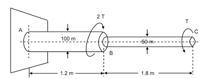
 The stepped steel shaft illustrated in Figure is subjected to a torque (T) at the free end and a torque (2T) in the opposite direction at the junction of the two sizes.

What is the net angle of twist at the free end, if the maximum shear stress in shaft is limited to 70 N/mm2?

Suppose the modulus of rigidity to the 0.84 × 10⁵ N/mm2.

227_Net angle of twist at the free end.png

Solution

Torque at C = T (anticlockwise)

Torque at B = 2T (clockwise)

 Maximum shear stress, τm = 70 N/mm2

G = 0.84 × 10⁵ N/mm2

Assume θ be the angle of twist at C.

Free Body Diagram

A reaction torque shall be induced at section A. Consider this torque be TA clockwise. Then total torque should vanish for equilibrium, thus,

TA  + TB  - TC  = 0


∴          TA  = TC  - TB  = T - 2T = - T

which means torque at A is equal to T in magnitude but opposite the supposed clockwise direction. TA is equal to T anticlockwise as illustrated in free body diagram of Figure .

1035_Net angle of twist at the free end1.png

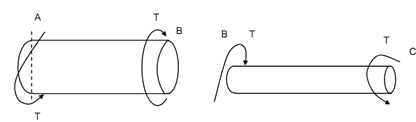
Figure: Free Body Diagram

The situation is that the equal torques T (but opposite in direction behaves on two portions). The similar magnitude of torque in BC shall induce higher stress than in AB because of diameters as illustrated in Figure. Hence, T should be determined from the portion BC.

T =  (π /16) τm d 3  = (π /16) × 70 × (50)3  = 17.2 × 10⁵  Nmm

J AB=  (π /32 )× (100)4  = 982 × 105  mm4

J BC =  (π/32 ) × (50)4  = 6.14 × 10⁵  mm4

The angle of twist is the difference of twist of C w.r.t. B and the twist of B with respect to A. (As two are in opposite directions).

θBC = T LBC / G J BC       (anticlockwise)

θ AC= T LAB / GJ AB           (clockwise)

θ=θAC   =   (T /G) [LBC/ J BC - LAB / J AB ]          (anticlockwise)

849_Net angle of twist at the free end2.png

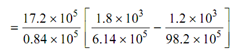
= (17.2 × 10⁵ /0.84 × 105)[   (1.8 × 10³/ 6.14 × 10⁵ ) - (1.2 × 10³  / 98.2 × 10⁵) ]?

= 20.5 [0.293 - 0.0122] × 10- 2

= 0.058 rad. = 3.3 deg.

or θ = 3o 18′


Related Discussions:- Net angle of twist at the free end - steel shaft

Benefits of cad, Quality Improvement : CAD can improve the quality of eng...

Quality Improvement : CAD can improve the quality of engineering design by increasing the efficiency and effectiveness of the designers. This can be observed with excellent

Essentials of a good boiler , ESSENTIAL S OF A GOOD BOILER: -     Sho...

ESSENTIAL S OF A GOOD BOILER: -     Should be capable of producing the required Steam at   the required pressure for minimum fuel required. -     Should be capable of stan

Supports for rigid bodies, Supports for Rigid Bodies: In this unit, yo...

Supports for Rigid Bodies: In this unit, you have learnt to classify various types of supports and constraints, rollers, rockers, ball and socket joints, cables, short links,

Trippaing, how thw trippaning process work

how thw trippaning process work

Determine the maximum permissible axial load, Determine the maximum permiss...

Determine the maximum permissible axial load: In an open coiled spring of 10 coils the stresses because of bending and twisting are 120 N/mm 2 and 150 N/mm 2 respectively wh

Evaluate boiler efficiency, The following data were obtained in a boiler tr...

The following data were obtained in a boiler trail: Mass and temperature of feed water: 680 kg/hr and 20 0 C, Steam temperature and its pressure : 15bar and 300 0 C, Coal used

Method of section, Method of section: Define the method of section? H...

Method of section: Define the method of section? How can you solve the problems with the help of method of section? Sol.: This method is powerful method for determining

If engine does not start at cranking speed troubleshooting , If Engine Does...

If Engine Does Not Start at Cranking Speed Causes of Problem Remedy Incorrect electrode gap of spark plug Fouled spar

Spring, direct shear and torsional shear of the coil

direct shear and torsional shear of the coil

Calculate the greatest stress - plate, Calculate the greatest stress - plat...

Calculate the greatest stress - plate: A rectangular plate 10 mm thick within a hole of 50 mm diameter drilled on this is as shown in Figure 10. This is subjected to axial pul

Write Your Message!

Captcha
Free Assignment Quote

Assured A++ Grade

Get guaranteed satisfaction & time on delivery in every assignment order you paid with us! We ensure premium quality solution document along with free turntin report!

All rights reserved! Copyrights ©2019-2020 ExpertsMind IT Educational Pvt Ltd