Modes of 8254-microprocessor, Assembly Language

Assignment Help:

Modes of 8254 :


1632_modes of 8254.jpg

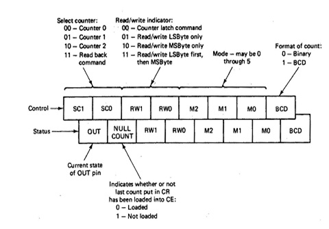
Mode 0 (Interrupt on Terminal Count)-GATE which value is 1 enables counting and GATE  which value is 0 disables counting, and GATE put not effect on OUT. The contents of the CR are transferred to CE on the first CLK pulse after CR is written into by the processor, unrelated of the signal on the GATE pin. Pulse that loads CE is not included in the count. OUT would low when there is an output to the control register and remains low till the count goes to 0.Primarily, Mode 0 is for event counting.

Mode 1 (Hardware Re -triggerabic  One-Shot)-After  CR has been loaded  with N, a 0-to-1  transition  on GATE will cause CE to be loaded, a one-to-zero transition  at OUT, and the count to start. When the count reaches to zero OUT will go high so producing a negative-going OUT pulse N clock periods long.

Mode 2 (Periodic Interval Timer)-after loading CR with N, a transfer is occur from CR to CE on the next clock pulse. OUT goes from one  to zero when the count becomes one and remains low for o1 CLK pulse; then it returns to 1 and CE is reloaded from CR, so  giving a negative pulse at OUT after each N clock cycles. GATE that value 1 enables the count and GAT that value is 0 disables the count. A 0-to-1 transition on GATE also causes the count to be reinitialized on the next clock pulse. This mode is utilized to provide a programmable periodic interval timer.

Mode 3 (Square-Wave Generator)-It is likewise to mode 2 except that OUT goes low when half the first count is reached and remains low till the count becomes zero. So the duty cycle is changed. As like before, GATE enables and disables the count and a zero to one transition on GATE reinitializes the count. This mode can be utilized for baud rate generation.

Mode 4 (Software-Triggered  Strobe)-It is likewise to mode 0 except that OUT is high while the counting is taking place and generate a one-clock-period negative pulse when the count reaches zero.

Mode 5 (Hardware-Triggered Strobe-Retriggerabic)-After CR is loaded, a O-to-I transition on GATE will cause a transfer from CR to CE during the next CLK pulse. OUT will be high in the time counting but will go low for one CLK period when the count becomes zero. GATE may reinitialize counting at any time.

For all modes, if the starting count is zero, it will be interpreted as216 or104 depending on the format of the count. The above descriptions were just to provide a whole idea of the operation of the 8254 in the several modes.


Related Discussions:- Modes of 8254-microprocessor

ADDITION-SUBTRACTION, HELLO I AM TRYING TO ADD AND SUBTRACT BUT I SEEM CAN'...

HELLO I AM TRYING TO ADD AND SUBTRACT BUT I SEEM CAN''T FIND THE CORRECT REGISTER TO PUT IN

Help with homework (python), i have trying to do the homework but there is ...

i have trying to do the homework but there is a mistake. (Counting positive and negative numbers and computing the average of numbers) write a program that reads an unspecified nu

Physical memory mapped and port input output-microprocessor, Physical Memor...

Physical Memory Mapped I/O and Port I/O : CPU controlled I/O comes in 2 ways. Simply the difference is whether we utilize the normal memory addresses for I/O, this is mention

Hi, i have a question.

i have a question.

Pin functions of 8086-microprocessor, Pin functions for the minimum mode o...

Pin functions for the minimum mode operation of 8086 are following: 1) M/I/O -Memory/IO: This is a status line logically equivalent to S2 in maximum mode. When it is low, it

Program for dispaying lcd characters, #include"lcd.asm"       ; assembly fi...

#include"lcd.asm"       ; assembly file is included for displaying lcd characters Main: PORTA EQU 0xF80  ; PORTS PORTB EQU 0xF81 PORTC EQU 0xF82 PORTD EQU 0xF83 R

Dq-dt-assemblers directive-microprocessor, DQ:   Define  Quad word:-  Th...

DQ:   Define  Quad word:-  This directive is taken in use to direct the assembler to reserve 4 words (8 bytes) of memory for the specified variable and can initialise it having

Machine level programs-microprocessor, Machine Level Programs In this s...

Machine Level Programs In this section, a few machine levels programming instance, rather then, instruction sequences are presented for comparing the 8086 programming with that

Assignment, 1. Write an assembly program that adds the elements in the odd ...

1. Write an assembly program that adds the elements in the odd indices of the following array. Use LOOP. What is the final value in the register? array1 DWORD 10, 20, 30, 40, 50, 6

The pin diagram of 8088-microprocessor, Pin diagram of 8088 : The pin ...

Pin diagram of 8088 : The pin diagram of 8088 is shown in given figure. Most of the 8088 pins and their functions are exactly similar to the corresponding pins of 8086.  Hence

Write Your Message!

Captcha
Free Assignment Quote

Assured A++ Grade

Get guaranteed satisfaction & time on delivery in every assignment order you paid with us! We ensure premium quality solution document along with free turntin report!

All rights reserved! Copyrights ©2019-2020 ExpertsMind IT Educational Pvt Ltd