Q. Measurement of poweri
A wattmeter is an instrument with a potential coil and a current coil so arranged that its defiection is proportional to VI cos θ, where V is the voltage (rms value) applied across the potential coil, I is the current (rms value) passing through the current coil, and θ is the angle between ¯V and ¯I. By inserting such a single-phase wattmeter to measure the average real power in each phase (with its current coil in series with one phase of the load and its potential coil across the phase of the load), the total real power in a three-phase system can be determined by the sum of the wattmeter readings. However, in practice, this may not be possible due to the nonaccessibility of either the neutral of the wye connection, or the individual phases of the delta connection. Hence it is more desirable to have a method for measuring the total real power drawn by a three-phase load while we have access to only three line terminals.
The three-phase power can bemeasured by three single-phasewattmeters having current coils in each line and potential coils connected across the given line and any common junction. Since this common junction is completely arbitrary, it may be placed on any one of the three lines, in which case the wattmeter connected in that line will indicate zero power because its potential coil has no voltage across it. Hence, that wattmeter may be dispensed with, and three-phase power can be measured by means of only two single-phase wattmeters having a common potential junction on any of the three lines in which there is no current coil. This is known as the two-wattmeter method of measuring three-phase power. In general, m-phase power can be measured by means of m - 1 wattmeters. The method is valid for both balanced and unbalanced circuits with either the load or the source unbalanced.
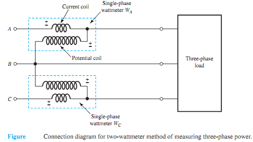
Figure shows the connection diagramfor the two-wattmetermethod ofmeasuring three-phase power. The total real power delivered to the load is given by the algebraic sum of the two wattmeter readings,
P = WA + WC
The significance of the algebraic sumwill be realized in the paragraphs that follow.Twowattmeters can be connected with their current coils in any two lines, while their potential coils are connected to the third line, as shown in Figure. The wattmeter readings are given by

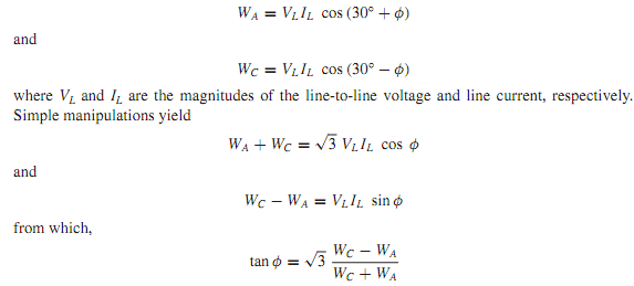
The two-wattmeter method, when applied to the balanced loads, yields interesting results. Considering either balanced wye- or delta-connected loads, with the aid of the corresponding phasor diagrams drawn earlier for the phase sequence A-B-C, it can be seen that the angle between ¯ VAB and ¯ IA is (30° + φ) and that between ¯VCB and ¯IC is (30 - φ), where φ is the load power factor angle, or the angle associated with the load impedance. Thus, we have
