Maximum stress in each material, Mechanical Engineering

Assignment Help:

The maximum stress in each material:

A copper tube of external diameter 60 mm and internal diameter 40 mm is closely fitted to a steel rod of 40 mm diameter to compose a composite shaft. If a torque of 6 kN-m is to be resisted by the shaft, discover the maximum stress in each material and the angle of twist in 2 m length.

Take  G = 80 kN/mm for steel, and

G = 40 kN/mm2 for copper.

Solution

Copper Tube

G = 40 kN/mm2  = 0.4 × 10¹¹ N/m2 , l = 2 m

d1 = 60 mm = 0.06 m

d2 = 40 mm = 0.04 m

2451_Maximum stress in each material.png

TC = torque resisted by copper tube

θ= Tl/ GJ    =  (TC ) (2) /((0.4 × 1011 ) (1 × 10- 6 )) = 2 TC × 10- 5 radians       ---------- (1)

τmax =  (T/J )× R = (1 × 10- 6 ) × (0.03) = 0.03 TC  × 10  N/m

         = 0.03 TC N/mm2                             ------------ (2)
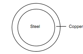
1689_Maximum stress in each material1.png

Figure

G = 80 kN/mm2  = 0.8 × 10¹¹ N/m2 ,   l = 2 m

d = 40 mm

J =  (π/32) d 4 = (π /32)× 0.044  = 2.5 × 10- 7 m4

R = 20 mm = 0.02 m

θ= Tl  / GJ  = (TS ) (2) / ((0.8 × 10¹¹ ) (2.5 × 10- 7 )) = TS × 10- 4 radians  --------- (3)

τmax =(T/ J) × R =  Ts / ((2.5 × 10- 7 ) (0.02)) = 0.008 TS  × 107  N/m

= 0.08 TS N/mm2                                    --------- (4)

In composite shafts, θC = θS

 ⇒        5 TC  × 10- 5  = TS  × 10- 4

∴          TC  = 2TS                                  -------- (5)

TS  + TC  = T

⇒         TS = 2TS  = 6

∴          TS = 2 kN-m             TC  = 4 kN-m

∴ Angle of twist, θ= (2 × 10³ ) × 10- 4  = 0.2 radians

Maximum Shear Stress

For copper shaft : For steel shaft :

τmax  = 0.03 × 4 × 103  = 120 N/m2

τmax  = 0.08 × 2 × 103  = 160 N/m2


Related Discussions:- Maximum stress in each material

Evaluate the stresses in the concrete and steel bars, A load of 1.9 MN is a...

A load of 1.9 MN is applied on a short concrete column 300mm x 300mm. The column is reinforced with four steel bars of 10mm diameter, one in each corner. Evaluate the stresses in t

F.M, what is viscosity?

what is viscosity?

Principal planes and principal stresses, Principal Planes and Principal Str...

Principal Planes and Principal Stresses: Define the Principal Planes and Principal Stresses. Sol.: When an element in strained body is under action of plane stresses, it i

Give shear force and bending moment diagrams, A simply supported beam ABC w...

A simply supported beam ABC with supports at A and B , 6m apart and with an overhang BC 2 metres long takes uniformly distributed load of 1.5 KN/metre length over the entair length

#, parameters in designing a presure vessels

parameters in designing a presure vessels

What are combined footings, What are combined footings? COMBINED FOOTIN...

What are combined footings? COMBINED FOOTINGS: When a footing supports two or more columns in the same line, it is called a combined footing. The combined footing which supp

Explain the end cutting edge angle, Explain the End Cutting Edge Angle ...

Explain the End Cutting Edge Angle It is an angle between the face of the tool and the plane perpendicular to side of shank. It acts as relief angle that is allows only small s

Evaluate resultant of the system - mechanics, Evaluate resultant of the sys...

Evaluate resultant of the system: Q: Figure given below shows two vertical forces and couple of moment 2000 Nm acts on horizontal rod, which is fixed at end A .  Determin

Write Your Message!

Captcha
Free Assignment Quote

Assured A++ Grade

Get guaranteed satisfaction & time on delivery in every assignment order you paid with us! We ensure premium quality solution document along with free turntin report!

All rights reserved! Copyrights ©2019-2020 ExpertsMind IT Educational Pvt Ltd