Maximum shear stress and angle of twist, Mechanical Engineering

Assignment Help:

Maximum shear stress and angle of twist:

Torques are applied on the shaft as illustrated in Figure. Discover in which portion of the shaft, maximum shear stress & angle of twist takes place.

139_Maximum shear stress and angle of twist.png

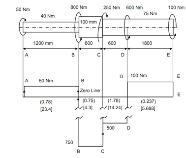
Figure: Torque Diagram

Solution

 Torque diagram is drawn below the shaft. For the cause a zero line is selected and clockwise torque is plotted above this line, that means upward and anticlockwise torque is plotted downward.

At A raise 50 Nm up, A to B the constant torque and 800 Nm down. Thus at section B

the torque TB = 800 - 50 = 750 Nm  924_Maximum shear stress and angle of twist1.png   From B to C constant torque and at C,

TC = 750 - 250 = 500 Nm924_Maximum shear stress and angle of twist1.png From C to D torque is constant and at D,

TD = 600 - 500 = 100 Nm668_Maximum shear stress and angle of twist2.png At E the torque is 100 -100 = 0. Therefore, highest torque acts on portion BC and TB = 750 Nm. For discover maximum stressed T/ d 3 portion check for . These values are written on torque diagram below zero line.

By Verifying the highest stress shall occur in portion CD.

τm = 16TC / π d 3 = 16 × 500 × 103/ π (75)3

= 6.036 N/mm2

The largest angle of twist is decided by largest value of Tl/ J or Tl/ d 4 . These values are written below the values of T/d3 on torque diagram.

 The largest twist occurs in portion AB.

θ max         = TA l / J G

=50 × 103 × 1200/ (π/32) (40)4 × 80 × 103

= 2.984 × 10- 3  rad = 0.171 deg.

= 10′ 15.5′′ C.


Related Discussions:- Maximum shear stress and angle of twist

Joint details and preparations, Joint Details and Preparations Joints s...

Joint Details and Preparations Joints shall be prepared by machining, flame cutting with grinding to bright metal or air-carbon arc gouging with grinding to bright metal such t

Explain process of casting and modeling, Explain desirable properties of mo...

Explain desirable properties of modeling and differentiate between the process of casting and modeling. Also highlight the advantages and disadvantages of casting process and model

Define the disadvantages of abrasive jet cutting machines, Define the Disad...

Define the Disadvantages of Abrasive Jet Cutting Machines Slow material removal rate. Stray cutting and hence accuracy is not good. Abrasive powder cannot be reused

Couple, a couple can be balanced by a force equal to its magnitude?

a couple can be balanced by a force equal to its magnitude?

Calculate for the resultant of the force system, Calculate for the resultan...

Calculate for the resultant of the force system: A rectangle ABCD is having sides AB = CD = 80 mm and BC = DA = 60 mm. Forces of 150 N each of them act along AB a

Effect of the parameters-spot welding, Effect of the parameters in spot wel...

Effect of the parameters in spot welding The passage of more current than what is required causes the following defects. I. Weld expulsion ii. Cavitations iii. Weld cracking

Splitwedge gate valve, Types of Splitwedge gate arrangement need to underst...

Types of Splitwedge gate arrangement need to understand

Write Your Message!

Captcha
Free Assignment Quote

Assured A++ Grade

Get guaranteed satisfaction & time on delivery in every assignment order you paid with us! We ensure premium quality solution document along with free turntin report!

All rights reserved! Copyrights ©2019-2020 ExpertsMind IT Educational Pvt Ltd