Magnetic permeability and the b/h curve, Electrical Engineering

Assignment Help:

Magnetic permeability and the B/H curve

To measure the relationship between field strength H and flux density B for a material, a sample is made into a closed ring and a magnetising coil wound onto it. Current flowing in this coil creates a m.m.f. equal to NI which in turn produces a magnetic field

H= NI/L

in the ring. So  H is proportional to the current in the energising coil and may be obtained from direct measurement of I. If a change in the current occurs, the flux density changes and this will induce a transient 'back e.m.f' in a second coil that is also wound onto the ring.


1372_Magnetic permeability and the B-H curve.png


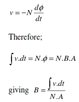
The integral of the back emf is proportional to B. Hence the relationship between B and H may be determined from measurement of I (to give H) and the induced back e.m.f in the coils (to give B).

The result of such measurements on various materials produces two types of curves - straight lines of low

B/H =µr

values and curves for  which the value of B/H =µr   varies. This first type are sub divided into paramagnetic
varies. This first type are sub divided into paramagnetic materials if B/H =µr >1 and diamagnetic if B/H =µr <1. The second type are ferromagnetic and have a more complicated dependence of B on H.  At low H these have B/H =µ>>1 (typically 100 - 100000)

85_Magnetic permeability and  B-H curve.png


It is also found that ferromagnetic materials lose these high µr properties above a well-defined temperature (different for different materials) known as the Curie temperature. This typically  r ranges from 200 - 750 °C and limits the maximum temperature that many electromagnetic devices can operate.


The temperature dependence of the ferromagnetic properties give a clue to the physical reason for the different

permeabilities of the materials. Diamagnetic and paramagnetic properties are attributable to the orbiting electrons within the atoms of the material. Ferromagnetic properties arise due to the orientation of atoms on a macroscopic scale so that the magnetic fields created by the orbiting electrons within each atom reinforce each other. These 'domains' of high magnetic strength may contain ~10-12   atoms each. The domains are initially randomly directed but under the influence of an external magnetic field, re-orientate to point in the same direction. Initially this is along the direction of the nearest crystal axis to the direction of the magnetic field.


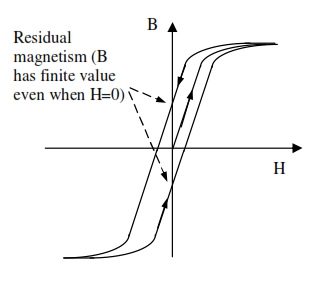
Steadily increasing the external field brings them directly into line with the external field direction.If the external field is now removed, the domains relax back to point in the nearest crystal direction, leaving a residual magnetism. Materials that have a strong residual magnetism are used for permanent magnets. Cycling the current over one complete cycle produces a hysteresis B/H curve


1726_hysteresis B-H curve.png


Related Discussions:- Magnetic permeability and the b/h curve

Variable capacitors, how can I simulate air variable capacitors in cst simu...

how can I simulate air variable capacitors in cst simulator?

PLC Programming, FIG. 2 Car Park Simulation Consider the above diagram, FI...

FIG. 2 Car Park Simulation Consider the above diagram, FIGURE 2, of the car park. The object of this assignment is to write a program to operate the barriers to allow the cars in

Determine the current in the circuit and the voltage, Q. Two identical junc...

Q. Two identical junction diodes whose volt-ampere relation is given by Equation in which IS = 0.1 µA, VT = 25 mV, and η = 2, are connected as shown in Figure. Determine the curren

How many electrons all semiconductor have in last orbit, All semiconductors...

All semiconductors in their last orbit have (A)  8 electrons.  (B) 2 electrons. (C)  4 electrons. (D)  6 electrons. Ans:     All semiconductors in their

find the thevenin and norton equivalent circuits, The output port of the o...

The output port of the one-port is defined by terminals A and B. Given: R 1 = 10 k_, R 2 = 20 k_, R 3 = 10 k_, and R 4 = 10 k_ V 1 = 20 V and I1 = 0.8 mA a) Find the T

Switching characteristics, Switching Characteristics Switching  charact...

Switching Characteristics Switching  characteristics  of BJT  are shown  in figure. Due  to the presence of internal  capacitances BJT  cannot be  turned  instantly. Initially

Explain atomic structure & energy band diagram of germanium, Explain Atom...

Explain Atomic structure and Energy Band Diagram of Germanium. Germanium : This is one of the most common semiconductor material utilized in the application in electronics.

What are plastics, What are plastics? Plastics are materials (containi...

What are plastics? Plastics are materials (containing carbon as common element) that have organic substances of high molecular weight and are able of being formed in required

Find the diode current and voltage in given circuit, We shall demonstrate l...

We shall demonstrate load-line analysis to find the diode current and voltage, and then compute the total power output of the battery source in the circuit of Figure (a), given the

Write Your Message!

Captcha
Free Assignment Quote

Assured A++ Grade

Get guaranteed satisfaction & time on delivery in every assignment order you paid with us! We ensure premium quality solution document along with free turntin report!

All rights reserved! Copyrights ©2019-2020 ExpertsMind IT Educational Pvt Ltd