Machine and Tool Selection
The quality of a product largely depends on the type of machine, the type of process, machining conditions and the right selection of tools. The current trend in manufacturing is to adopt more and more of automation of the fixed and flexible type. Hence, with a machine tool of a given level of automation the scope for improving productivity lies more and more in the selection and application of cutting tools.
Some of the factors influencing the selection of cutting tool are properties of tool materials, properties of work materials, the type of process, the accuracy and surface finish required, the cutting conditions, tool wear and tool life. The properties of tool material include Hardness, strength, Stiffness and Resilience, Wear resistance, Low coefficient of friction, Thermal Conductivity and Specific Heat. Some important tool materials used are High Carbon Steels, High Speed Steels, Cast Cobalt (Stellite) Tools, Carbides, Coated Carbides, Ceramics, Diamonds, Cubic Boron Nitride(CBN), Polycrystalline Diamond.
The important properties influencing the selection of cutting tools are : Hardness, Tensile strength, Modulus of elasticity, Chemical composition, Micro structure, Strain hardenability and thermal conductivity. The type of the manufacturing process depends upon the type of the tools used. Basically the tools can be classified into two types generating tools and forming tools. At the time of process planning the tools are selected depending on the accuracy and surface finish required. This is because of the fact that different operations and different tools would produce different accuracy levels and surfaces.
The tool life equation as proposed by Taylor is VTn = C
where n = Constant for tool material,
V = Cutting speed, m/min, and
T = Tool life in min.
As this formula doesn't take into account all the effecting parameters, many researchers have extended this formula.
TQB = C
Equation 2
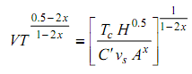
where H = Specific heat × thermal conductivity,
θ = Tool temperature,
A = Area of cut,
us = Specific cutting energy/unit cutting force, and
C and x are constants.
VTn f n1, dn2 = C . . . (3)
where f = Feed, mm/rev.,
d = Depth of cut, and
C = Constant.
All the cutting tools used in lathe are single point tools. The single point cutting tool nomenclature comprises the various parts of tool and systematic arrangement of tools angles. The tool angle are normally specified in the sequence of Back rake, Side rake, End relief, Side relief, End cutting edge, Side cutting edge angles and Nose radius. The various operations performed on a lathe machine are centering, turning, facing, thread cutting, knurling, parting off, forming, drilling, boring, and reaming. Similarly this unit discusses about the other type of tools used in milling and drilling.