At the completion of this unit, you will be able to determine the cutoff frequencies and attenuations of RC and RL low- and high-pass filters by using test circuits.
UNIT FUNDAMENTALS
A filter is a frequency-selective circuit that permits signals of certain frequencies to pass while it rejects signals at other frequencies.
A low-pass filter, as its name implies, passes low frequencies but rejects high frequencies.
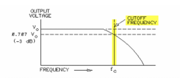
The dividing line between the passing of low frequencies and the rejecting of high frequencies is the cutoff frequency (fc), or -3 dB point. In a low-pass filter, signals lower than the cutoff frequency pass essentially unmodified. Frequencies higher than the cutoff frequency are greatly attenuated, or reduced.
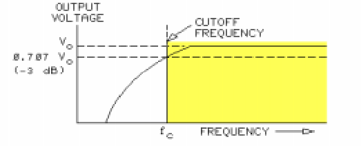
In a high-pass filter, signals higher than the cutoff frequency pass essentially unmodified. Signals lower than the cutoff frequency is greatly attenuated, or reduced.
The cutoff frequency (fc) is the point where the output voltage (Vo) drops to 70.7% of, or 3 dB down from, the input voltage.
Frequency response data may be expressed in terms of output voltage but is usually expressed in decibels (dB). Decibels are units that express or measure the gain or loss (attenuation) in a circuit. The decibel can be based on the ratio of the output voltage (Vo) to the input voltage (Vi).

NOTE: In the type of filters studied in this volume, the output voltage (Vo) is always less than the input voltage (Vi).
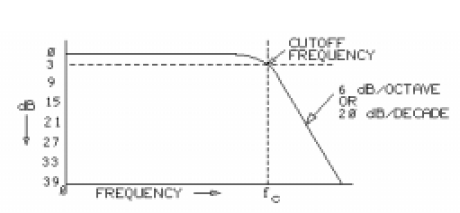
The rate of attenuation, or loss, beyond the cutoff frequency (fc) is highly predictable. This attenuation is 6 dB per octave or 20 dB per decade. An attenuation rate of 6 dB per octave is the same rate as 20 dB per decade.
NEW TERMS AND WORDS
band - a range of frequencies.
dB per octave - decibels per octave (dB/octave); a 1 dB increase or decrease over a two-to-one frequency range.
dB per decade - decibels per decade (dB/decade); a 1 dB increase or decrease over a ten-to-one frequency range.
octave - a two-to-one or one-to-two ratio; a frequency factor of two. One octave is the doubling or halving of a frequency.
decade - a ten-to-one or one-to-ten ratio; a frequency factor of ten.
rolled off - gradually attenuated, or decreased. A filter attenuates when its rejected frequencies are rolled off.
EQUIPMENT REQUIRED
F.A.C.E.T. base unit
AC 2 FUNDAMENTALS circuit board
Oscilloscope, dual trace
Generator, sine wave
Exercise 1 - Low-Pass Filters
EXERCISE OBJECTIVE
When you have completed this exercise, you will be able to calculate the cutoff frequencies and attenuations of RC and RL low-pass filters. You will verify your results with an oscilloscope.
DISCUSSION
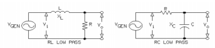
- Several ways exist for the implementation of low-pass filters, each of which consist of a voltage-divider network containing a resistor and a frequency-varying component (inductor or capacitor).
- Output voltage from the filters is "tapped off" the voltage divider.
- Changes in the frequency of the supply voltage cause changes in the circuit reactance, resulting in output voltage variations.
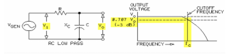
- In RC filters, the capacitive reactance is high at low frequencies compared to the resistance, causing most of the input voltage to appear across the output capacitor.
- Capacitive reactance decreases as the generator frequency increases, causing larger voltage drops across the R and decreasing the voltage across the output capacitor.
- Low-pass filters are designed so that frequencies below the cut-off frequency are passed while higher frequencies are attenuated.
- In low-pass RL filters, the inductive reactance is small at low frequencies compared to the resistance, and most of the input voltage falls across the output resistor.
- Inductive reactance increases as the generator frequency increases; therefore, more and more voltage is dropped across the inductor and less across the output resistor.
- Cutoff frequency is defined as the frequency where the output signal is 3 dB down, or 0.707 x Vo.
- For RC circuits: fc = 1/2πRC
- For RL circuits: fc = R/2πL