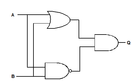
'Exclusive or' gate:
The basic OR gate illustrated previously in Figure 3 was seen to include the AND operation in that its output will adopt the 1 state not only when either input A or input B is at the 1 state but also when BOTH inputs are at 1. There are many occasions in logic circuits when it is required to perform the OR operation only when input A or input B are exclusively at the 1 state. In other words, a gate is required whose output adopts the 1 state only when the two input states are not identical, and such a device is known as the EXCLUSIVE OR gate.
As an example, suppose the problem is to implement the following logical statement:
"A room has two doors and a central light, and switches are to be fitted at each door such that either switch will turn the light on and off".
By fitting double-pole changeover switches at each door, a switching circuit could be wired to perform the required operation as shown in Figure 6. If each switch position is designated 'down' for the 1 state and 'up' for the 0 state, then symbols can be allocated to each switch position as shown in the diagram. If the lamp L is designated 1 for ON and 0 for OFF, then the truth table will show the circuit conditions for the switching combinations.
As the EXCLUSIVE OR gate can occur frequently in a logic circuit, it has been allocated its own special symbol, as shown in Figure, with an equivalent circuit shown at Figure.
Also, in Boolean algebra expressions, a CIRCLE SUM ⊕ symbol is often employed to signify that a particular expression represents the EXCLUSIVE OR operation.
