Layout and operation of typical thrust reversing system, Other Engineering

Assignment Help:

Layout and operation of typical thrust reversing system:

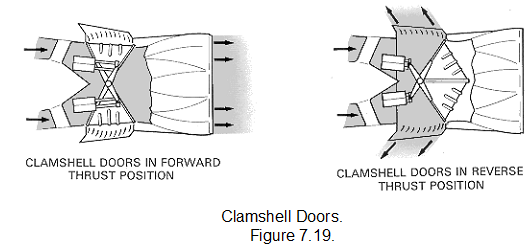
Clamshell door system

The clamshell door system is a pneumatically operated system, as shown in detail in fig Normal engine operation is not affected by the system, because the ducts through which the exhaust gases are deflected remain closed by the doors until reverse thrust is selected by the pilot.

On the selection of reverse thrust, the doors rotate to uncover the ducts and close the normal gas stream exit. Cascade vanes then direct the gas stream in a forward direction so that the jet thrust opposes the aircraft motion.

The clamshell doors are operated by pneumatic rams through levers that give the maximum load to the doors in the forward thrust position; this ensures effective sealing at the door edges, so preventing gas leakage. The door bearings and operating linkage operate without lubrication at temperatures of up to 600 deg.C.

375_Layout and operation of typical thrust reversing system.png

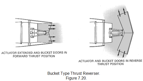
Bucket target system

The bucket target system is hydraulically actuated and uses bucket-type doors to reverse the hot gas stream. The thrust reverser doors are actuated by means of a conventional pushrod system. A single hydraulic powered actuator is connected to a drive idler, actuating the doors through a pair of pushrods (one for each door).

The reverser doors are kept in through the drive idler. The hydraulic actuator incorporates a mechanical lock in the stowed (actuator extended) position.

In the forward thrust mode (stowed) the thrust reverser doors form the convergent-divergent final nozzle for the engine.

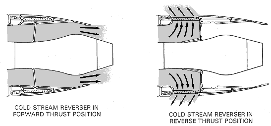
Cold stream reverser system

The cold stream reverser system can be actuated by an air motor, the output of which is converted to mechanical movement by a series of flexible drives, gearboxes and screwjacks, or by a system incorporating hydraulic rams.

When the engine is operating in forward thrust, the cold stream final nozzle is 'open' because the cascade vanes are internally covered by the blocker doors (flaps) and externally by the movable (translating) cowl; the latter item also serves to reduce drag.

On selection of reverse thrust, the actuation system moves the translating cowl rearwards and at the same time folds the blocker doors to blank off the cold stream final nozzle, thus diverting the airflow through the cascade vanes.


1743_Layout and operation of typical thrust reversing system1.png

2105_Layout and operation of typical thrust reversing system2.png


Related Discussions:- Layout and operation of typical thrust reversing system

Seekers , Seekers   There are two main types of sensor used in autono...

Seekers   There are two main types of sensor used in autonomous vehicles (seekers and position/attitude sensors) - although not all systems have both.            - Airc

Keplers’s three laws of planetary motion, Expertsmind.com brings you uniqu...

Expertsmind.com brings you unique solution in electrical engineering -          Ancient people kept track of time and seasons as it affected agriculture. -          Some

Assembly buildings - fire risk assessment, Assembly buildings: Assembl...

Assembly buildings: Assembly buildings are high life risk premises.  People often very densely occupy such buildings and they do so in large numbers so they must be given good

Vlsi, Working of bi- CMOS invertor in vlsi

Working of bi- CMOS invertor in vlsi

Avionic systems design- stability derivatives, The idea of stability deriva...

The idea of stability derivatives is to approximate the general functional relationship between any force ormoment variable and the dynamic or control variables as a Taylor series

The operational amplifier , The operational amplifier : The integrated ...

The operational amplifier : The integrated circuit operational amplifier is one of the most useful and versatile electronic devices available today.  The name 'operational ampl

Engine vibration indication, Engine Vibration Indication The engine vib...

Engine Vibration Indication The engine vibration monitoring (EVM) system shows the out of balance force for the N1 and N2 shaft. High engine vibration shows engine damage or

Flight dynamics - pitching moment, The centre of pressure (CP) is defined a...

The centre of pressure (CP) is defined as the point about which the resultant moment is zero; the net effect of the flow in terms of forces and moments would be the same as if the

Write Your Message!

Captcha
Free Assignment Quote

Assured A++ Grade

Get guaranteed satisfaction & time on delivery in every assignment order you paid with us! We ensure premium quality solution document along with free turntin report!

All rights reserved! Copyrights ©2019-2020 ExpertsMind IT Educational Pvt Ltd