Laser-induced breakdown spectroscopy (LIBS) is a type of spectroscopy that uses plasma generated by a laser pulse. A schematic of a LIBS system is shown in the figure. The laser is focused on the sample and forms plasma, which atomizes and excites samples. LIBS have the capabilities of analyzing any material regardless of its composition (solid, liquid or gas). When a material breaks down and forms plasma of sufficient temperature, it emits light at characteristic frequencies (spectrum) that corresponds to the material. LIBS can (in principle) detect all elements, limited only by the power of the laser and the spectral sensitivity of the spectrometer & detector. The detection limit of the LIBS spectrometer is a function of a) the plasma temperature b) spectral pass band of the optical system, and c) the strength of the spectral emission being viewed.
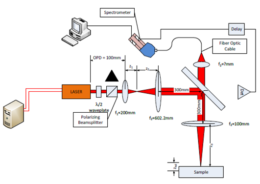
Figure: Layout of a Laser Induced Breakdown Spectrometer
The LIBS system presented in Figure 1operates by focusing the laser onto a small part of the sample with sufficient power to ablate a very small amount of material. Typically only a few nanograms of material ablated from the sample. This ablated material generates a plasma plume with temperatures in excess of 100,000 K. This plasma quickly cools to a temperature in the range of 5,000-20,000 K. At these temperatures the plasma plume is imaged. When the plasma is first formed it emits a continuum of light (i.e. white light) When the plasma cools and expands the spectral lines of the elements present in the plasma start to be observable. The delay between viewing the emission of continuum radiation and the spectral signature of the materials present is approximately 10 μs from the laser pulse.
Transmission Path
The laser source is a 1064nm Nd:YAG laser with a pulse width of 10ns. The average output power of the laser is 750W. The waist location is at the output window of the laser and has a diameter of 1mm. Assuming that it takes an intensity of 3.4 GW/cm2 to ablate the surface of the material of interest, what is the diameter of the beam on the sample? What F# is necessary to achieve this spot size? If the focal length of the lens is 100mm what is the Diameter of the lens (f3)? If the output of the laser has a diameter of 1mm and is a waist of the laser, determine the distances z1 and z2. Determine the distance z3. Calculate the radius of the beam assuming a Gaussian profile. Assuming it takes more than 75% of the peak intensity to form plasma, determine the tolerance on the sample location. (How accurate do you need to place the sample to get a signal?)
Receiver Path
One of the advantages of LIBS is that the spectrometer that is used to analyze the plasma spectrum can be separated from the event by a distance with the use of a fiber optic cable. Assume for this design that the fiber optic cable is an 8/125 cable made of fused silica. For the purpose of this problem take the index of refraction of the core to be 1.46 and the cladding to be 1.42. What is the NA, the acceptance angle, Θc, andΘ ¯ of the fiber? How many modes propagate down the fiber? Using this information, what is the focal length of the lens used to focus the light from the plasma into the fiber? At the other end of the fiber is a grating, lens, and linear CCD array. Sketch the configuration of this system used to collect the light diffracted by the diffraction grating onto the CCD Array. The grating has a Θ = 2000nm. What is the range of angles diffracted for a wavelength range from 400nm to 1000nm? Assuming that each pixel of the CCD array is 5 microns and that there are 4096 pixels in the linear array. What is the focal length of the lens? What is the wavelength resolution of the CCD Array?