It should include all the theory that you need to complete the requested design, and all the simulation documents that you produce after synthesizing the circuit. Briefly, your report should include the followings:
o Introduction: It should include the theory behind the design; e.g. the logic expressions, the circuit operation and the circuit applications.
o Design Problem: It includes only the problem statements.
o Design Procedure: It must include, in details, your plan of what you need in order to solve the problem with all derived logic expressions, truth tables, optimization procedures, etc.
o Simulation Results: It should include the circuits' schematics, VHDL codes, functional and timing simulation waveforms, reports on the propagation delays, and your observations on the hard copies.
o Conclusion: It must include your comments on the problem, design procedure, CAD System, simulation results, and anything came up during your work.
As long as the licensed version of Quartus II is only available in our instructional laboratory (IH203), the student has to contact the instructor in order to have an access. Note that everybody MUST work individually and his report should reflect his own understanding to the subject.
DESIGN STATEMENT
JK Flip-Flop:
Write VHDL code that represents a JK flip-flop. Use behavioral code rather than structural code. Synthesize a circuit using CAD tools. Simulate the circuit that verifies the desired functionality.
Johnson Counter:
Write VHDL code that represents an eight-bit Johnson counter. Synthesize the code using CAD tools. Simulate the circuit showing the counting sequence.
Bus Structure:
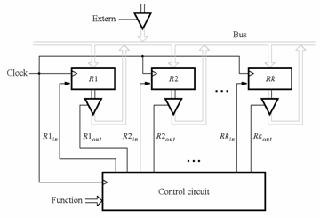
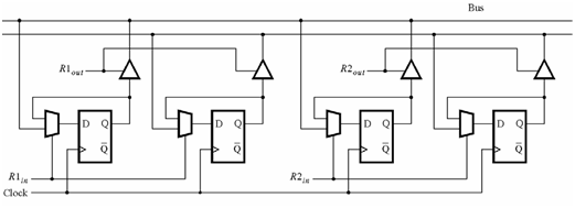
Implement the schematic of the following circuit using the CAD tools.
Use

Use the VHDL code as an entry design for the following figure that describes the details for connecting registers to a bus. (Hint: Using Figures 7.61 and 7.62 in the textbook).

Also write the VHDL code that can be used as an entry design for the following figure that describes the control circuit. (Hint: Modify the VHDL code in Figure
Synthesize the circuit for your schematic and simulate.