Interrupt System Based on Multiple 8259As
A multiple 8259A interrupt system is diagrammed in given figure in this figure data bus drivers are not indicated, but they could be inserted. Although the SP/EN pin on the master 8259A is linked to the data bus transceivers, a 0 is applied to the SP/EN pins of the slaves. Only one slave is shown, but up to 7 more slaves could be in the same way connected into the system, allowing up to 64 distinct interrupt request lines. When designing the address decoder logic, each 8259A might be given its own address pair in the I/O address space. The drivers insert in the CAS2-CASO lines may/ may not be required, depending on the proximity of the master to the slaves.
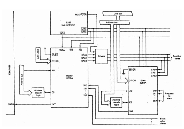
In a multiple 8259A system the slaves might be initialized as the master is initiated. The master would be initialized in the same way as described above except that SNGL would be set to value 0 and the ICW3 would required to be filled. A 1 would be put in each of the ICW3 bit for which the equivalent IR bit is associated to a slave and 0s would be put in the remaining bits. The SFNM bit can be set to value 1 to activate the special completely nested mode. The SNGL bit should also be set to 0 when initializing the slaves. Thus, an ICW3 will be needed for each of the slave, but for a slave ICW3 has apart meaning from it. For a slave, ICW3 has the form
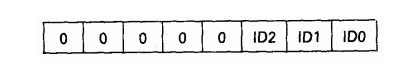
where the 3 least significant bits provide the slave with an specific identification number. The identification number given to the slave should be the similar as the number of the master request line to which its INT pin is associated.
When a slave puts a value 1 on its INT pin this signal is sent to the suitable IR pin on the master. Suppose that the IMR and priority resolver do not block this signal, it is sent to the CPU through the INT pin on the master. When the CPU returns the INTA signal the master will not only set the suitable ISR bit and clear the corresponding IRR bit, it will also check the equivalent bit in the ICW3 to know whether or not the interrupt came from a slave. If it came, the master will place the number of the IR level on the CAS2- CASO lines; if it is not, it will put the contents of the ICW2on the data bus and no signals will be applied to the CAS2- CASO lines. The INTA signal is also retained by all of the slaves, but only that slave who's ID matches the number sent to it by the master on the CAS2-CASO lines will accept the signal. In the selected slave the suitable ISR bit will be set, the corresponding IRR bit will be cleared, and its ICW2 will be put on the data bus. Because the ICW2 consist the interrupt type, it is essential that unique combinations be put in the master and the slave both ICW2s during the initialization procedure. The EOI commands are needed for the master and the slave both if their AEOI bits are value 0.