A very widely used alternative form of synchronous motor is the 'induction motor'. This has the advantage that it does not require an auxiliary motor to run the rotor up to synchronous speed.
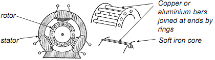
The rotor consists of stout copper (or aluminium) conductors arranged in the form of a cylindrical cage (commonly known as a 'squirrel cage' rotor). These are laid in slots in a soft iron core that focuses the magnetic flux produced by the stator across the bars of the cage and all the bars are electrically connected together at each end by copper (or aluminium) rings.
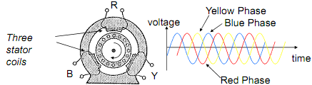
Three stator windings arranged at 120° to each other around the rotor are energised by the three phases of an ac supply and this creates a magnetic field that rotates at the frequency of the supply.
With the rotor stationary, the rotating magnetic field induces an emf in the cage that in turn drives a current through its conductors (an 'eddy' current). This current reacts against the magnetic field to produce a torque that causes the rotor to turn in the direction of the rotating magnetic field.
If the rotor were to rotate at the same speed as the rotating magnetic field, then it would not experience any change in the magnetic field and no emf would be induced in the rotor.
No current (and therefore no torque either) would then be induced in the rotor.
Some torque will always be needed to overcome mechanical losses (friction, air resistance etc) in addition to any mechanical load applied to the motor, so in practice the rotor always turns more slowly than the rotating magnetic field.
The fractional difference in speed between the rotational speed of the magnetic field (the synchronous speed) and that of the rotor is called the 'slip'.
Slip = Synchronous speed - Rotor speed
Synchronous speed
NOTE:
(1) The larger the torque applied to the motor, the greater the slip required to produce the torque needed.
(2) Because of the slip, the frequency of the induced currents in the rotor is less than that of the applied stator voltage. The induced voltage is proportional to the rate of change of the magnetic field strength as 'seen' by the rotating armature.
(3) If the slip is small, the frequency of the currents flowing in the rotor is low and so the effect of any inductance of the rotor is negligible. (Z=j L). In this case, only the resistance of the rotor limits the current in the rotor (and hence the torque produced by the motor).
So: Torque = K.S/R
where K is a constant for a given machine.
Advantages: no brushes or slip rings are required - relatively easy and cheap to make. Reliable (no sliding electrical contacts). Smooth torque output.
Disadvantages: operates at one speed (determined by the frequency of the three-phase ac supply used). Needs electronic controllers to produce variable frequency supplies if required to operate at variable speeds.
Normally needs three-phase supplies (it is possible to use single phase supplies from which other phases can be derived by phase-shifting circuits).
Applications: aircraft fuel pumps, (that are immersed in fuel to aid cooling), fans, conveyer belt drives, pumps etc.