Q. Illustrate Master-Slave Flip-Flop?
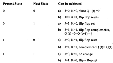
Master slave flip-flop comprise two flip-flops. One is master flip-flop and other one is known as slave flip-flop. Fig below shows implementation of master-slave flip-flop employing J-K flip-flop.

Figure: Master - Slave flip- flop
Note: Master-slave flip-flop can be constructed using D or SR flip-flop in similar way.
(i) When clock pulse is 0 master flip-flops is disabled however slave becomes active and its output Q & Q¯ becomes equivalent to Y and Y¯ correspondingly. Why? Well possible combination of value of Y and Y' are either Y=1, Y¯ =0 or Y=0 Y¯ =1. So slave flip-flop can have subsequent combinations: -
(a) J=1, K=0 that means Q=1, Q =0 (stet flip-flop)
(b) J=0, K=1 that means Q=0, Q =1 (clear flip-flop)
(ii) when inputs are applied at JK and clock pulse becomes 1 only master gets triggered resulting in intermediary output Y going to state 0 or 1 relying on input and previous state. Remember during this time slave is also preserving its previous state only. As clock pulse becomes 0 master becomes inactive and slave obtains same state as master as described in (a) and (b) conditions above.
However why do we need this master-slave combination? To realize this consider a situation where output of one flip-flop is going to be input of other flip-flop. Here assumption is that clock pulse inputs of all flip-flops are synchronized and happen at same time. The change of state of master happens when clock pulse goes to 1 however during that time output of slave still hasn't changed So the state of flip-flops in system can be changed concurrently during the same clock pulse even though output of flip-flops are linked to inputs of other flip-flops.