Illustrate core losses in magnetic core material, Electrical Engineering

Assignment Help:

Q. Illustrate Core Losses in magnetic core material?

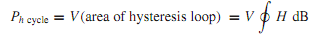
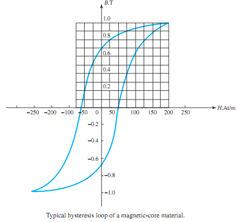
Iron-core losses are usually divided into two components: hysteresis loss and eddy-current loss. The former is proportional to the area enclosed by the hysteresis loop, shown in Figure,

which is a characteristic of a magnetic core material. The area of the loop represents the heat - energy loss during one cycle in a unit cube of the corematerial. The hysteresis loss per cyclePh cycle in a core of volume V, possessing a uniform flux density B throughout its volume, is given by

387_Illustrate Core Losses in magnetic core material.png

The hysteresis loss per second is approximated empirically by

1383_Illustrate Core Losses in magnetic core material1.png

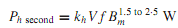
where kh is a proportionality constant dependent on the characteristics of iron, f is the frequency of excitation in hertz, and Bm is the maximum value of the core flux density. This loss component of the core loss can be reduced by choosing a core of electrical steel that has a narrowhysteresis loop. Square-loopmagneticmaterials (such as ferrites and permalloy) that have a nearly rectangular hysteresis loop are used in switching circuits, as storage elements in computers, and in special types of transformers in electronic circuits.

Another feature of an ac-operated magnetic system is the eddy-current loss, which is the loss due to the eddy currents induced in the core material. The eddy-current loss is empirically approximated as

457_Illustrate Core Losses in magnetic core material2.png

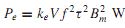
where ke is a constant dependent on the characteristics of iron, V is the volume of iron, f is the frequency, τ is the lamination thickness (usually a stack of thin laminations makes up the core), and Bm is the maximum core flux density. By choosing very thin laminations (making τ smaller), the eddy-current loss can be reduced.

The laminations (or thin sheets), insulated from each other by a thin coat of varnish, are oriented parallel to the direction of flux, as shown in Figure. Laminating a core generally results in an increase in the overall volume. The ratio of the volume actually occupied by the

63_Illustrate Core Losses in magnetic core material3.png

magnetic material to the total (gross) volume of the core is known as the stacking factor. The thinner the lamination thickness, the lower the stacking factor. This factor usually ranges between 0.5 and 0.95.


Related Discussions:- Illustrate core losses in magnetic core material

Determine active power-reactive power, Three equal impedances of D ohms res...

Three equal impedances of D ohms resistance and C inductive reactance are connected in a DELTA configuration. The line voltage is A00 volts. Determine the line current, phase cur

Complete the timing diagram of an sr latch, Complete the timing diagram of ...

Complete the timing diagram of Figure of an SR latch.

Variable capacitors, how can I simulate air variable capacitors in cst simu...

how can I simulate air variable capacitors in cst simulator?

Compute the attenuation, Q. A rectangular air-?lled RG-52/U is made of bras...

Q. A rectangular air-?lled RG-52/U is made of brass (ρ = 3.9 × 10⁻⁸ m) and has dimensions a = 22.86 mm and b = 10.16 mm. (a) Determine ¯ Z0(= R0) at the limits of the practica

Explain interrupts of 8085, Explain Interrupts of 8085. a) Maskable  in...

Explain Interrupts of 8085. a) Maskable  interrupt b)  Vectored interrupt c)  Non maskable interrupt d) Hardware interrupt e)  Software interrupt

The time constant of the field winding, The field winding of a 200 V d.c. m...

The field winding of a 200 V d.c. machine has a resistance of 20? and an inductance of 500mH. Calculate: (a)  The time constant of the field winding (b)  The value of curr

Explain shockly''s equation and its significance, Q. Explain shockly's equa...

Q. Explain shockly's equation and its significance in plotting the transfer characteristics ? The linear relationship does not exists in the output of the JFET, the relationshi

Find the transmitters unmodulated carrier power, At the transmitter in a st...

At the transmitter in a standard AM system, P f = 50 W. In the receiver (S 0 /N 0 ) AM = 250 when (S i /N i ) AM = 3000. Find the transmitter's unmodulated carrier power and t

Determine the maximum length, Q. If the line of Problem 15.1.3 is made of c...

Q. If the line of Problem 15.1.3 is made of copper whose resistivity ρ = 1.72×10 -8 ·m, determine the maximum length that can be used if losses are not to exceed 3 dB when f = 3

Determine the induced armature emf, A250-V, 50-kWshort-shunt compound dc ge...

A250-V, 50-kWshort-shunt compound dc generator,whose schematic diagramis shown in Figure, has the following data: armature resistance 0.05 , series-field resistance 0.05 , and sh

Write Your Message!

Captcha
Free Assignment Quote

Assured A++ Grade

Get guaranteed satisfaction & time on delivery in every assignment order you paid with us! We ensure premium quality solution document along with free turntin report!

All rights reserved! Copyrights ©2019-2020 ExpertsMind IT Educational Pvt Ltd