IGNITION SYSTEMS
The outline of a high energy ignition system is illustrated in the figure. Each high energy ignition unit has a low voltage supply which is controlled by the control unit in the starting system. Depending upon the engine and installation, the supply voltage may be either direct current (DC) or alternating current (AC). If the supply is DC, either a trembler mechanism or a transistor generator is used to convert the dc input to low voltage ac. Thereafter, the operation is the same as that of the system supplied with AC:-
• The low value of AC is stepped up to a high value by a transformer.
• The high value alternating voltage is then ‘rectified' to provide a high value of DC voltage which is used to charge a capacitor.

• When the capacitor voltage is high enough, it breaks down a discharge gap and the discharge is applied to the igniter plug where the energy (high voltage, high current) is converted to a spark across the face of the igniter plug.
Construction
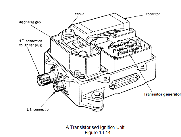
A modern transistorised version of a high-energy ignition unit is illustrated in figure 13.14. Although the construction varies according to the type of ignition unit, the basic operation is as described. A choke is fitted to extend the duration of the discharge and safety resistors are fitted to ensure dissipation of energy in the capacitors.
Lethal Warning
The electrical energy stored in the HE ignition unit is potentially lethal and, even though the capacitor is discharged when the electrical supply is disconnected, safety precautions are necessary. Before handling the components, the associated circuit breaker should be tripped, or the fuse removed. Never rush in; at least one minute must be allowed between disconnecting the power supply and touching the ignition unit, HT lead or igniter plug.

IGNITER PLUG
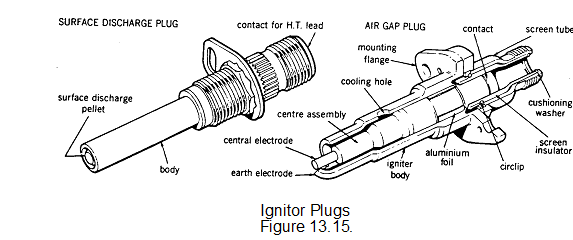
There are two basic types of igniter plug; the constricted or constrained air gap type and the shunted surface discharge type. (fig. 13-15)
The air gap type is similar in operation to the conventional reciprocating engine spark plug, but has a larger air gap between the electrode and body for the spark to cross. A potential difference of approximately 25,000 volts is required to ionise the gap before a spark will occur. This high voltage requires very good insulation throughout the circuit.
The surface discharge igniter plug has the end of the insulator formed by a semi-conducting pellet which permits an electrical leakage from the central high tension electrode to the body. This ionises the surface of the pellet to provide a low resistance path for the energy stored in the capacitor. The discharge takes the form of a high intensity flashover from the electrode to the body and only requires potential difference of approximately 2000 volts for operation.
The normal spark rate of a typical ignition system is between 60 and 100 sparks per minute. Periodic replacement of the igniter plug is necessary due to the progressive erosion of the igniter electrodes caused by each discharge.
The igniter plug tip protrudes approximately 0.1 inch into the flame tube. During operation the spark penetrates a further 0.75 inch. The fuel mixture is ignited in the relatively stable boundary layer which then propagates throughout the combustion system.

SERVICING THE IGNITION SYSTEM
Before any servicing is carried out on an ignition system, you must read the relevant Safety Notes together with the Maintenance Manual relating to this work. You must, in particular, understand the lethal warning notice regarding handling high energy ignition equipment and the safety precautions you are to observe.