High pressure gas hazards, Electrical Engineering

Assignment Help:

High Pressure Gas Hazards

When we consider the dangers of compressed gas in the lab, there are three main sources of danger as follows:

1) Sudden release of high pressure gas

2) Gas cylinders as unstable heavy objects

3) Inherent dangers of the contents of gas cylinders

It is advisable to know as to what general precautions should be taken when handling gases, or even to know the dangers of particular gases. None of this knowledge is of much use to you if you don't actually know what gas is inside the cylinder. The main indication is given on the shoulder of a cylinder where the name and chemical formula of the gas should appear. A secondary indication of the gas or its nature is given by colour coding as follows:

i) Ground colours - covering the entire cylinder body

ii) Colour bands - on the shoulder of the cylinder.

2353_Gas cylinder with colour coding.png

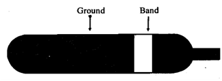
Figure: Gas cylinder with colour coding.

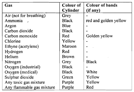
The ground colours tell you what the gas is, and the bands tell you something about the nature of the gas. Table 1 1.1 summarises the important markings which should be learnt by heart.

Table: Gas cylinder colour codes.

149_Gas cylinder colour codes.png

In addition to the colour codes, flammable gases are usually indicated by cylinders being fitted with a left-hand thread. Of course this indication is only of use when fitting a valve and regulator to a cylinder. However, you need to know which way to turn when removing the valve unit.


Related Discussions:- High pressure gas hazards

Electromagnetic torque , Electromagnetic torque  The torque is given...

Electromagnetic torque  The torque is given by the force on the armature winding multiplied by its radius. Force on a conductor in magnetic field B is:  F=B.I.L so, T=B

What is memory mapping, What is memory mapping? The assignment of memor...

What is memory mapping? The assignment of memory addresses to several registers in a memory chip is known as memory mapping.

Explain how to represent power lines, Explain How to Represent Power Lines?...

Explain How to Represent Power Lines? The equivalent circuit of a power line depends on the length of the line and on the accuracy of the model required. In general, any power

Sketch the d.c. equivalent circuit of the amplifier, Question: Figure s...

Question: Figure shows the basic circuit of the BJT Common Emitter Amplifier. (a) What is the function of RB, RC, Ci, Co and CE ? (b) (i) Sketch the d.c. equivalent circu

Determine the efficiency when the transformer, A 3-kVA, 220:110-V, 60-Hz, s...

A 3-kVA, 220:110-V, 60-Hz, single-phase transformer yields these test data: • Open-circuit test: 200 V, 1.4 A, 50 W • Short-circuit test: 4.5 V, 13.64 A, 30 W Determine th

Zener diode, how does a zener diode works.

how does a zener diode works.

Define the objectives of load flow analysis, Define the Objectives of Load ...

Define the Objectives of Load Flow Analysis The objectives of load flow analysis are: (i) To analyse an existing power system, future expansion or a new power system plan.

Introduction to electronics, Explain the difference between a microprocesso...

Explain the difference between a microprocessor and an embedded microcontroller

Determine voltage and current gain, Q. Determine voltage and current gains ...

Q. Determine voltage and current gains for the CE BJT amplifier shown in Figure with the following parameters: R 1 = 30,000, R 2 = 9000 ,R C = 750 ,R E = 250 , R L = 1000 

Write Your Message!

Captcha
Free Assignment Quote

Assured A++ Grade

Get guaranteed satisfaction & time on delivery in every assignment order you paid with us! We ensure premium quality solution document along with free turntin report!

All rights reserved! Copyrights ©2019-2020 ExpertsMind IT Educational Pvt Ltd