The aim of this project is for you to discover how to use a spreadsheet to "model" a typical engineering problem, in this case a heat transfer situation. And to discover how this model can be used to solve problems that would otherwise require lengthy analytical or trial and error solutions. The model can then be used as a design/analysis tool to try out various "what if" scenarios. Hot oil is used as an alternative to steam for providing process heat in some industries. In our scenario the hot oil is being pumped to the process equipment through an insulated pipe and we want to determine the rate of heat loss per metre of pipe. The pipe is made from mild steel and is insulated with fibreglass and clad with stainless steel. Heat is being lost from the stainless steel cladding surface by convection and by radiation. The initial problem is to determine the heat loss and cladding surface temperature for various thicknesses of the fibreglass insulation.
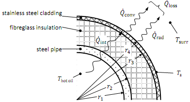
The following data is given: hot oil temperature, ...................................... 180°C
steel pipe internal diameter, ..................................................... 80 mm
steel pipe external diameter, .................................................... 90 mm
pipe length, ................................................................................. nominal, 1 m
inside convection heat transfer coefficient, ............................. 50 W/m2°C
steel pipe thermal conductivity, .......................................... 35 W/m°C
initial fibreglass insulation thicknesses ........................................... 25 mm
insulation thermal conductivity, ......................................... 0.039 W/m°C
stainless steel cladding thickness ................................................... 2.6 mm
stainless steel cladding thermal conductivity, ........................ 14 W/m°C
stainless steel emissivity, .................................................... 0.2
outside convection heat transfer coefficient, ........................ 18 W/m2°C
ambient/surrounding surface temperature, ......................... 22°C
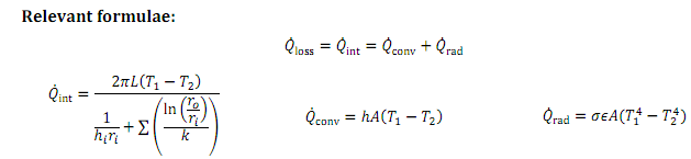
At first glance this looks to be a relatively simple problem, however to solve it we need to find the surface temperature, before we can find the heat loss,. To solve for analytically would require the solution of a polynomial (quartic) equation. With the spreadsheet we can solve this fairly easily using a trial and error approach or using one of the advanced tools available in Excel to automate this process...
Specific requirements:
You are required to:
Set up a spreadsheet model of the heat transfer situation, using Microsoft Excel, as detailed below.
Write a Report (Word document) with comments and results as also detailed below.
1. Spreadsheet Model
Set up your spreadsheet model of the heat transfer situation with an area for input values (all of the data given above), an area for intermediate answers (eg radii, Qint, Qconv, Qrad), and an area for the final results, Ts and Qloss. Your model should be set up to be as flexible as possible to produce answers for and for a given insulation thickness. (Imagine other engineers might use your spreadsheet as a tool for similar heat loss situations, so make it clear, easy to use and helpful).
In your Report (Word document) :
Explain how you set up the spreadsheet and what "advanced" functions or tools you used, and how you used them to solve for s and loss for a given insulation thickness.
Provide a table summarising your results ( Ts and Qloss ), for the following insulation thicknesses:
25 mm, 50 mm, 75 mm and 100 mm.