FUEL FLOW METERING:
Fuel flowmeters are fitted in aircraft to give an accurate indication of the rate at which fuel is being used and the total amount of fuel that has been used at any point during the flight. From the rate of fuel consumption the pilot is able to determine the performance of his engines, and from the indication of the total fuel consumed, can calculate the total flying hours that the aircraft can remain in the air.
There are a number of different types of fuel flowmeters in use on various aircraft and it is beyond the scope of this publication to describe them all. Some of these flowmeters indicate only the total fuel consumed, but the majority give indications of both rate of flow and total fuel consumed.
The volumetric flowmeter shown in figure. has a turbine rotor with a magnet inset into one of the vanes. When the rotor rotates it induces a pulse in the induction coil. The bore of the unit is calibrated to cause the rotor to rotate 32 times for every pound of fuel passing through it. The pulses are passed through a system of circuits similar to the speed probes mentioned earlier. This type of flowmeter can indicate flow in gallons or litres. Although it is calibrated in pounds per hour, this figure is only accurate at one S.G. or temperature. A similar system using a moving vane in a toroidal chamber is available, again only accurate at one S.G.
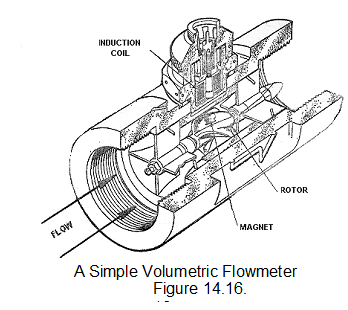
To indicate mass flow accurately a flowmeter that compensates for changes of S.G. is required.
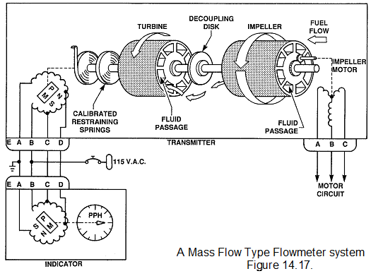
The mass flow type of flowmeter gives a reading of the mass flow rate in pounds or kilograms per hour rather than a volumetric reading in gallons per hour. The mass flow rate is a more useful indication for most types of aircraft. Refer to figure 14.17. for a mass flowmeter. The mass flowmeter consists of a motor-driven impeller, a turbine and a synchro system to transmit the data to a flightdeck gauge. In order to give accurate readings, the impeller must be driven at a constant speed. This is accomplished with an AC synchronous motor or a similar device. As the fuel flows through the impeller, it is given a spin or rotation by the spinning impeller. When the fuel leaves the impeller, it strikes the turbine, which is rotated against a restraining spring by the spin energy of the fuel. Because a denser fuel would impart more spin energy to the turbine the degree of rotation of the turbine is a measure of mass flow rate. The turbine is connected to the transmitter rotor of a synchro system which will cause the pointer on the flightdeck gauge to rotate to the proper position to indicate the correct mass flow rate. The sensor for this and other types of flowmeters is installed in the fuel system downstream of the fuel control device so that the flow rate represents the fuel consumption rate for that engine.
There are other type of mass flow transmitters, that use swirl vanes to cause the rotation and have a different type of detection system, or vane type with complicated S.G. correction.
The flowmeter gauge will have a flow indicator and usually a fuel used indication. The fuel used indicator is usually a digital read-out that is derived by integrating the fuel used with time.