Fuel control in Aircraft Engine:
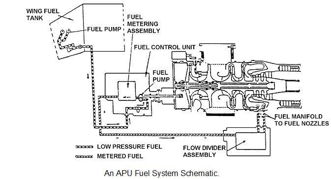
The basic fuel system is comprised of a fuel pump that receives low-pressure fuel from the aircraft fuel tank via a low pressure fuel valve and pumps it at a higher pressure to the fuel nozzles as shown in figure 18.14. Since the nozzle has resistance to flow, the fuel pressure rises in the fuel line between the pump and nozzle. The fuel is divided into primary and secondary flow by a fuel flow divider before being sprayed into the combustor and, with the addition of a spark, then combustion is initiated.
The fuel pump is designed to supply more fuel than required by the APU as shown in the figure 18.15.
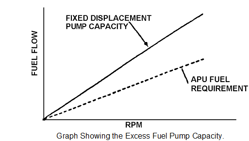
The upper line represents fuel flow from the pump. As pump speed increases so does the pump output capacity.
The lower line represents APU fuel requirements.
Some means must be available to remove the excess fuel capacity.
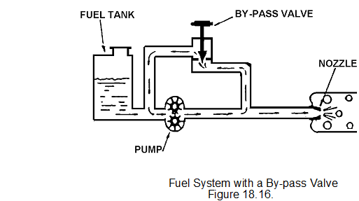
By adding a by-pass valve a method of controlling the fuel pressure and thus the engine. If the by-pass valve is closed, all the fuel is directed to the nozzle. Opening the by-pass valve will allow fuel back to the inlet of the pump, thus reducing the fuel to the nozzle. By controlling the by-pass valve, the operator can vary the amount of fuel to the nozzle.
Such control in fact is done automatically by the APU fuel control unit.
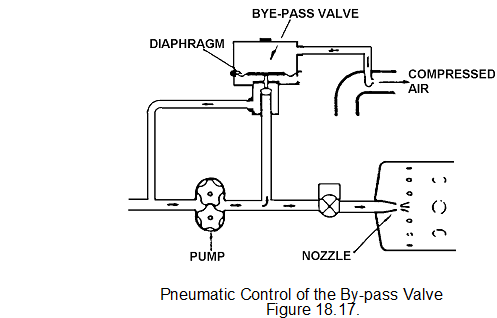
Figure fuel pressure is applied to the lower part of the by-pass ball valve. An air tapping which protrudes into the compressor airstream, applies pressure to the upper part of the by-pass valve diaphragm, thus holding the valve on its seat. Therefore fuel pressure is limited by the air pressure.
When initial ignition takes place within the APU, there is little air pressure, so fuel pressure cannot rise very much without pushing the valve open and allowing the excess fuel to go to the pump inlet. Because of the size of the diaphragm and valve, the air pressure allows the fuel pressure to rise by a proportional amount, thus fuel and air pressure stay in step with each other.
As engine speed increases:-
• Compressor pressure rises.
• Fuel pressure rises.
A minimum fuel pressure is required for good fuel atomisation at the fuel nozzle for initial ignition. This is achieved by applying a spring pressure to the by-pass valve, thus keeping it on its seat.
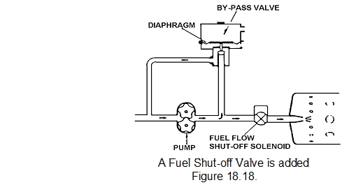
Figure shows a solenoid operated shut-off valve fitted between the FCU and the fuel nozzle. Normally spring-loaded closed; it receives its open and close signals from the APU control unit at certain speeds. On a mechanical APU it is signalled open by the low oil pressure switch when oil pressure is sensed. In an electronic system it is open at speeds above 10%. On receiving a closed signal, the solenoid de-energises and the valve closes, the flow to the combustor is blocked. The build-up in pressure in the fuel line is relieved by the by-pass valve, acting as a pressure relief valve.
As the engine accelerates, some means must be provided to enable more fuel to be injected into the combustor. This is achieved by a flow divider.
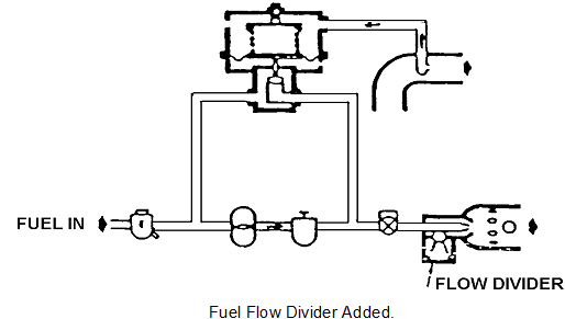
In the flow divider, one nozzle is placed within the other and separated by a small pressure relief valve. The flow divider is set for a slightly higher pressure than the by-pass valve spring pressure, thus on initial light-up, fuel will only spray from the primary nozzle.
After light-up, rising compressor pressure increases the by-pass valve setting and the fuel pressure increases to force the flow divider off its seat. This allows fuel flow through to the secondary nozzle as well as the primary nozzle.
During start and acceleration, the APU must produce temperatures that are within certain limits, while at the same time allow the engine to accelerate.
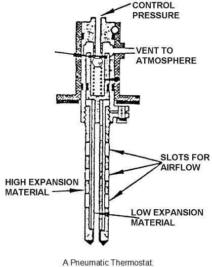
Despite the fact that fuel pressure is kept in step with rising compressor pressure (through the by-pass valve), turbine over temperature is possible during certain acceleration phases. As a protection against over temperature, a thermostat (known as acceleration thermostat) is connected to the air pressure line, leading to the by-pass valve, this thermostat is normally closed.
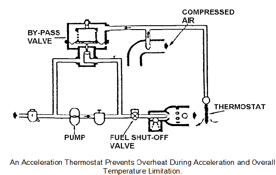
Provided the EGT remains below the thermostat setting, it will remain fully closed. If the EGT exceeds its setting, the thermostat will gradually open and bleed off air pressure that is acting on top of the diaphragm of the by-pass valve.
This reduced air pressure against the by-pass valve diaphragm will allow the fuel pressure to lift the by-pass valve and direct excessive fuel pressure back to the inlet of the pump. As the fuel pressure drops across the nozzles, the turbine temperature drops until the thermostat closes at a lower safe limit.
The acceleration thermostat provides a continuous monitor to prevent the APU engine overtemping. A second pneumatic thermostat is fitted to control the air load valve which is similar to the acceleration thermostat.
The thermostat can be adjusted in two ways, shimming or vernier adjuster. Shimming requires careful calculations to set the correct pressure on the ball. The vernier type adjuster has indications around the top of the thermostat, when it is unlocked the top can be twisted to make the adjustment.