Frame Buffers - Graphics Hardware
The storage region in a raster scan display system is set as a two-dimensional table. All row-column entry stores information as brightness or and colour value of the consequent pixel on the screen. Inside a frame buffer all pixel can be presented through 1 to 24 or more bits depending upon the quality resolution of the display system and specific attributes of the pixel. Higher the resolution betters the feature of the pictures. Commands to plan a line or point are transformed in colour and intensity values of the bitmap or pixel array of an image by a process termed as Scan Conversion.
The display set-up cycles by the refresh buffer, row-by-row at speeds of 30 or 60 times per second to generate the image upon the display. The intensity values picked up by the frame buffer are routed to the Digital to Analog converter that generates the essential deflection signals to produce the raster scan. A flicker- free image is twisted by interlacing all odd-numbered scan lines which are displayed first from just top to bottom and after that, all even-numbered scan lines which are displayed. The effectual refresh rate to generate the picture turns into much greater than 30 Hz.
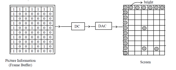
Figure: If information stored in frame buffer is 1 then, the corresponding pixel is made bright on the screen and if it is zero then no brightness appears i.e., 0→off; 1 → ON so the image obtained on the screen is discrete.
Various kinds of memory have been utilized in frame buffers: The earliest kind of frame buffers utilized drums and disks along with rotational frequency compatible to the rate of refresh. That frame buffers were termed as rotating-memory frame buffers. Although the relatively lower prices of integrated circuit shift registers saw the rotating-memory frame buffer being replaced through the shift-register frame buffers. A frame buffer can be assembled with a number of shift registers, all representing one column of pixels on the screen. All shift register supplies one bit per horizontal scan line. Conversely, changing a specified spot on the screen is not very simple with shift registers. Consequently they are not appropriate for interactive applications.
Modern frame buffers utilize random-scan integrated circuits where the pixel intensities are represented through 1, 2, 4,8,16 or 24 bits. Encoding text and easy images does not need more than say, 8 bit per pixel. Although to generate a good quality coloured image more than 8 bits, anything as 24 bits, are needed. One of the best processes to encode coloured pictures involves the utilization of a colour map. The pixel values in the frame buffer are treated like addresses of a look-up-table that has entries for all pixels' red, green and blue elements. The entry value is utilized to control the intensity or colour on the Cathode ray tube; the entire colour components can be explained to high precision giving precise control over the colours displayed.
The other type of frame buffer is the numerous-plane frame buffer; here the frame buffer can be functioned as consisting of some frames or planes, all containing information as intensity or colour, values of a separate image. An eight-bit per pixel frame buffer can be made to present a single image along with eight-bits of intensity precision or this can present tow images each of four-bit intensity precision or eight black and white images along with 1-bit intensity precision all. A variety of image mixing can be completed. For illustration, in animation set-up, some moving objects can be displayed like separation planes.