Flag Register :
8086 has a 16-bit flag register which is divided into 2 parts, viz. (a)machine control flagsand (b)condition code or status flags. The condition code flag register is the lower byte of the 16-bit flag register along with the overflow flag. The condition code flag register is equal to 8085 flag register, with an additional overflow flag, which is not present in 8085. This division of the flag register of 8086 reflects the results of the operations performed by ALU. The control flag register is the largerbyte of the flag register of 8086. It has 3 flags, viz. 1)direction flag (D),2) interrupt flag 3) and trap flag (T). Total bit configuration of 8086 flag register is shown in given figure
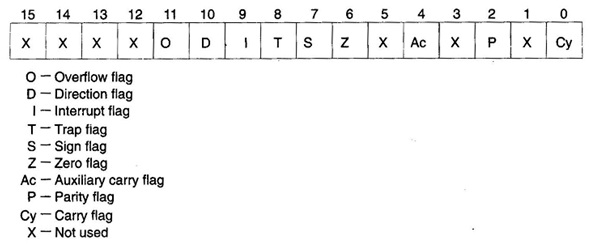
Figure: Flag register of 8086
Following are the description of each flag bit
1) S-Sign Flag: This flag is set, when the result of any computation is negative, the sign flag equals the MSB of the result for signed computations.
2) Z-Zero Flag: This flag is set, if the result of the computation orcomparison performed by the earlierinstruction/instructions is 0.
3) P-Parity Flag: This flag is set to 1, if the lower byte of the result contains even number of 1's.
4) C-Carry Flag: This flag is set, when there is perform of MSB in case of addition or borrow in case of subtraction. i.e. when 2 numbers are added, a carry can be generated out of the most significant bit position. In this case the carry flag will be set to '1'. In case, no carry is generated, it will be'0'. Some other instructions also affect or use this flag and will be discussed later in this text.
5) T-Trap Flag: If this flag is set, then the processor enters the single step execution mode. In the other words, a trap interrupt is generated after execution of every specificinstruction. The processor executes the current instruction and the control is transferred to the Trap interrupt service routine.
6) 1-lnterrupt Flag: If this flag is set, the mask able interrupts are recognised by the CPU, otherwise, they are ignored.
7) D-Direction Flag: This is used by string manipulation instructions. If this flag bit is '0', the string is processed starting from the lowest address to the highest address, for example autoincrementing mode. Or else, the string is processed from the highest address towards the lowest address, for example. Autodecrementing mode. We will discuss string manipulations later in chapter 2 in more details.
8) Ac-Auxiliary Carry Flag: This is set, if there is a carry from the lowest nibble, for instance. Bit 3, during addition or borrow for the lowest nibble, for example bit 3, during subtraction.
9) O-Overflow Flag: This flag is set, if an overflow occurs, for example if the result of a signed operation is large enough to be accommodated in a destination register. For example, in case of the addition of 2 signed numbers, if the outcome overflows into the sign bit, for example the result is of more than 7-bits in size in case of 8-bit signed operations and more than 15-bits in size in case of 16-bit signed operations, and then the overflow flag shall be set up.