Find out the smallest force:
A block weighing 800 N is raised up with the help of two 6o wedges B and C of negligible weights as illustrated in Figure. If the coefficient of static friction is 0.25 for all surfaces of contact, find out the smallest force P to be applied to raise the block A.
Solution
Let us primary draw the free body diagrams for block A and wedges B and C. Block A is in contact with the vertical wall and the horizontal surface of block B. Thus, the normal reactions N1 and N2 will be perpendicular to the respective surfaces of contact as illustrated in Figure. The direction of movement of block A w.r.t. the wall being vertically upwards, the direction of frictional force shall be vertically downwards as friction opposes the motion. Likewise, the motion of block A w.r.t. wedge B being towards right, the direction of frictional force at the surface of contact of block A and the wedge shall be towards left as illustrated in the free body diagram of block A.
Figure 3.17 : Free Body Diagram of Block A
In the restricting condition, we know F1 = μ N1 and F2 = μ N2. Thus, there are only two unknowns : N1 and N2 and two equations of equilibrium being available, we may find the values of N1 and N2.
∑ Fx = 0 ∴ N1 - F2 = 0
∴ N1 = F2 = 0.25 N 2
∑ Fy = 0 ∴ N2 - W - F1 = 0
∴ N 2 - 800 - 0.25 N1 = 0
∴ N 2 - 800 - 0.25 (0.25 N 2 ) = 0
∴ N 2 (1 - 0.0625) = 800
∴ N 2 = 800 / 0.9375
= 853.33 N
Now let us draw the free body diagram of wedge B. Keeping in mind that the frictional forces oppose the motion, and the normal reactions, as the name recommend, are perpendicular to the surfaces of contact; the several forces acting on wedge B shall be as indicated in the free body diagram of wedge B illustrated in Figure.
Figure 3.18 : Free Body Diagram of Wedge B
Applying the equations of equilibrium, we have following:
∑ Fy = 0 ∴ N3 cos 6o - N2 - F3 sin 6o = 0
∴ N3 cos 6o - N 2 - 0.25 N3 sin 6o = 0 (as F3 = 0.25 N3)
∴ 0.9945 N3 - 853.33 - 0.0261 N3 = 0
∴ N3 = 853.33 /0.9684 = 881.18 N
And, ∑ Fx = 0
∴ F2 + F3 cos 6o + N3 sin 6o - P = 0
∴ P = F2 + F3 cos 6o + N3 sin 6o
= 0.25 N 2 + 0.25 N 3 cos 6o + N3 sin 6o
Putting the values of N2 and N3, we have
P = 0.25 × 853.33 + 0.25 × 881.18 cos 6o + 881.18 sin 6o
= 213.33 + 219.09 + 92.11
= 524.53 N
Thus, a force of 524.53 N shall be required to raise the block A.
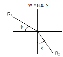
You may also solve the problem by constructing the triangle of forces R1, R2 and W for block A, where R1 is the resultant reaction of N1 and F1 and R2 is the resultant reaction of N2 and F2.
As the three forces keep the block in equilibrium, the forces should be concurrent. This may be solved graphically or by using Lami's theorem for three concurrent forces.
By applying Lami's Theorem, we obtain:
W / sin (90o + 2 φ) = R1 / sin (180o - φ) = R2 / sin (90o - φ)
where
φ = angle of friction
= tan -1 μ = tan -1 (0.25)
= 14.036 o
∴ R2 = W cos φ / cos 2 φ
= W cos 14.036o / cos 28.072o
= (800 × 0.9701 )/0.8823
= 879.61 N
Figure
Likewise, for wedge B, there are three forces acting : R2, R3 and P where,
R2 = Resultant reaction of N2 and F2
R3 = Resultant reaction of N3 and F3
The three forces acting shall be as illustrated in Figure
Figure 3.20
By applying Lami's theorem, we have
R2 / sin (90o + φ + 6o ) = Psin (180o - 2 φ - 6o ) = R3 / sin (90o + φ)
∴ P = R2 sin (2 φ + 6o)/ cos (φ + 6o)
= 879.61 sin 34.072o /cos 20.036o
= 524.53 N