Find out force on each member - Truss:
A truss is as shown in the figure given below. Find out force on each member and the nature of it.
Sol.: First we calculate support reaction, Draw FBD as shown in figure given below
Determine forces in all members of truss loaded and supported as shown in the figure given below.
Sol.: The reaction at the supports is determined by considering equilibrium of entire truss. As both the external loads are vertical, only vertical component of reaction at hinged ends A required to be considered. As the ?AEC is a right angle ?, having angle AEC = 90º. Then,
AE = AC cos 60º = 5 X 0.5 = 2.5m
CE = AC sin60º = 5 X 0.866 = 4.33m
As? ABE is an equilateral triangle and thus,
AB = BC = AE = 2.5m
The distance of line of action of force 10KN from the joint A,
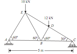
AF = AE cos 60º = 2.5 X 0.5 = 1.25m
Again, ?BDC is a right angle ? having angle BDC = 90º. Also, BC = AC - AB = 5 - 2.5 = 2.5m
BD = BC cos 60º = 2.5 X 0.5 = 1.25m
The distance of line of action of force 12KN from the joint A,
AG = AB + BG = AB + BD cos 60º = 2.5 + 1.25 X 0.5 = 3.125m
By taking moment about end A,
RC X 5 = 12 X 3.125 + 10 X 1.25 = 50
RC = 10KN ...(i)
∑V = 0, RC + RA = 10 + 12 = 22KN
RA = 12KN ...(ii)
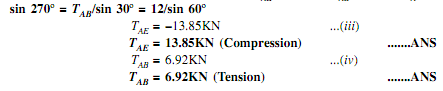
Joint A:
Consider free body diagram of joint A as shown in figure given below Let, TAE = Force in the member AETAB = Force in member AB Direction of both the forces (TAE and TAB) is taken away from the point A. As the three forces are acting at the joint A. Thus apply lami's theorem at A.TAE/sin 270º = TAB/sin 30º = RA/sin 60º TAE/

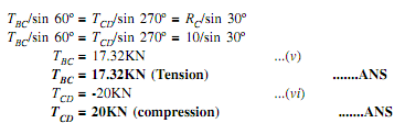
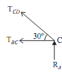
Consider free body diagram of joint C as shown in given figure Assume,
TBC = Force in member TBC and TCD = Force in member CD Direction of both the forces (TBC & TCD) is taken away from point C. As the three forces are acting at joint C. So apply lami's theorem at point C.
 =
=
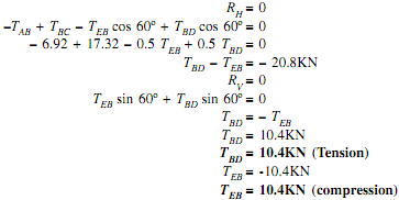
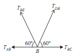
Joint B:
Consider free body of joint B as shown in fig.
As, TAB = 6.92KN
TBC = 17.32KN
Let, TBD = Force in member BD
TEB = Force in member EB
Direction of both forces (TBD and TEB) is taken away from point B. As the four forces are acting at joint B. Thus apply resolution of forces at the B.
Joint D:
Consider free body diagram of joint D as shown in the figure.
As, TCD = -20KN
Let, TED = Force in member ED
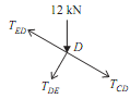
Direction of force (TED) is taken away from the point D. As the four forces are acting at joint D. Thus apply resolution of forces at the joint D.
Resolve all the forces along EDC,
TED + 12cos 60º + TCD = 0
TED + 6 - 20 = 0
TED = 14KN ...(xi)
TED = 14KN (Tension) .......ANS
|
Member
|
AE
|
AB
|
BC
|
CD
|
BD
|
BE
|
DE
|
|
Force in KN
|
13.85
|
6.92
|
17.32
|
20
|
10.4
|
10.4
|
14
|
|
Nature
C = Compression
T = Tension
|
C
|
T
|
T
|
C
|
T
|
C
|
T
|