Find out deflection under the load, Mechanical Engineering

Assignment Help:

Find out Deflection under the load:

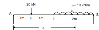
A beam of span 4 m is subject to a point load of 20 kN at 1 m from the left support and a Udl of 10 kN/m over a length of 2 m from the right support.

Find out :

1. Slope at the ends.

2. Slope at the centre.

3. Deflection under the load.

4. Deflection at the centre.

5. Maximum deflection.

Take EI = 20 × 106 N-m2.

Solution

∑ Fy  = 0, so that RA + RB  = 20 + 10 × 2 = 40 kN         --------- (1)

275_Find out Deflection under the load.png

Figure

Taking moments around A,

RB  × 4 = 20 × 1 + 10 × 2 × 3 = 80

RB  = 20 kN                                                      -------- (2)

RA  = 20 kN

M = 20 x - 20 [ x - 1] - 10 [ x - 2] ([ x - 2]/2)

= 20 x - 20 [ x - 1] - 5 [ x - 2]2

EI (d 2 y/ dx2) = M

= 20 x - 20 [ x - 1] - 5 [ x - 2]2       ---------- (4)

 EI (dy / dx )= 10 x2 /3 - (10/3) [ x - 1]2  - (5/3) [ x - 2]3  + C1        ------ (5)

EIy = 10 x3 /3- (10/3) [ x - 1]3  - ( 5/12) [ x - 2]4  + C 1 x + C2  ---------6

at A, x = 0,      y = 0,        C2  = 0

at B, x = 4 m,      y = 0

0 =(10 × 43 )/3- 10 (4 - 1)3 - (5/12)  (4 - 2)4  + C 1 × 4

C1 =- 29.17

EI dy/ dx = 10 x2  - 10 [ x - 1]2  - (5 /3 )[ x - 2]3  - 29.17

 (a)       Slope at A, (x = 0),

θ A = - 29.17 / EI = - 29.17 × 10/(20 × 106)

 = - 1.46 × 10- 3  radians

(b)        Slope at B, (x = 4 m),

EI θB  = 10 × 42  - 10 (4 - 1)2  - 5 (4 - 2)3  - 29.17 = + 27.5

θB = + 1.38 × 10- 3  radians

 (c)       Slope at centre, (x = 2 m),

EI θC  = 10 × 22  - 10 (2 - 1)2  - 29.17

θC  = + 0.04 × 10- 3  radians

Deflection under the load :

EIy = 10 x3 /3- 10 [ x - 1]3  - (5/12)  [ x - 2]4  - 29.17 x

At x = 1 m,

EIy D = (10/3) - 29.17

EIyD  = - 25.84 × 103 × 103/20 × 106

= - 1.29 mm

 (d)      Deflection at the centre :

           x = 2 m

EIy =10 × 23 - (10/3) (2 - 1)3 - 29.17 × 2

yC  = - 1.75 mm

 (e)       Maximum deflection : Let the maximum deflection b/w D and C (x < 2 m).

dy/ dx = 0

10 x2  - 10 ( x - 1)2  - 29.17 = 0

10 x2  - 10 x2  - 10 + 20 x - 29.17 = 0

x = 1.96 m < 2 m

EIy max = (10/3) (1.96)3  - 10 (1.96)3  - 29.17 × 1.96 = - 35

∴ ymax  = - 1.7501 mm


Related Discussions:- Find out deflection under the load

Where pneumatic system is used, Any system needs redundancy in work needs p...

Any system needs redundancy in work needs pneumatics, because the compressor of the pneumatic system has periodical operations (intermittent work, not as hydraulic pump). The compr

#power plant, Components of power plant &it''s functions

Components of power plant &it''s functions

Determine the moment of resistance of the flitched beam, Determine the mome...

Determine the moment of resistance of the flitched beam: A flitched beam consists of a wooden beam of width 120 mm & depth 250 mm & mild steel plates of thickness 10 mm & widt

Direct current, Direct Current Using direct current, the tungsten el...

Direct Current Using direct current, the tungsten electrode may be connected to either the negative or the positive terminal of the supply of power. In almost all cases, ele

How is bearing capacity of soil varied, How is bearing capacity of soil var...

How is bearing capacity of soil varied? The bearing capacity of soil varies not only with its strength but also with the magnitude and distribution of the load. When a load Q,

Projectles on an inclined plane, a misile is fired at speed v and an angle ...

a misile is fired at speed v and an angle m that is inclide at an angle r to the horizontal.calculate the range

Generation of steam at constant pressure - thermodynamics, Generation of st...

Generation of steam at constant pressure: Steam is pure substance. Like any other pure substance it can also be converted into any of the three states, that is, solid, liquid

Determine frequency of free oscillations, (a) Illustrate critical damping a...

(a) Illustrate critical damping and its uses. (b) A horizontal spring mass system with coulomb damping has a mass of 5 Kg attached to a spring of stiffness 1KN/m. if the coeffic

Shear and moment diagrams, Shear and Moment Diagrams Determine the anal...

Shear and Moment Diagrams Determine the analytical solution for the maximum stress of the beam shown; compare with stress results from Solid Works. Draw shear and moment diagra

Write Your Message!

Captcha
Free Assignment Quote

Assured A++ Grade

Get guaranteed satisfaction & time on delivery in every assignment order you paid with us! We ensure premium quality solution document along with free turntin report!

All rights reserved! Copyrights ©2019-2020 ExpertsMind IT Educational Pvt Ltd