Fet parameters, Electrical Engineering

Assignment Help:

FET Parameters

A basic, low-frequency hybrid-pi model for the MOSFET is displayed in figure. The several parameters are as follows.

369_FET parameters 2.png

is the transconductance in siemens that evaluated in the Shichman-Hodges model in terms of the Q-point drain current ID by:

946_FET parameters 1.png

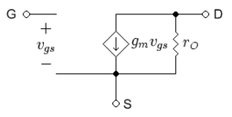
                                                     Figure: Simplified, low-frequency hybrid-piMOSFET model.

gm = 2ID /VGS = Vth ,

In which:

ID stands for the quiescent drain current (also called the drain bias or DC drain current)

Vth stands for the threshold voltage and

VGS stands for gate-to-source voltage.

The combination:

VoU = (VGS - Vth)

Often is called the overdrive voltage.

375_FET parameters 3.png

is the output resistance because of channel length modulation, calculated by using the Shichman-Hodges model as

ro = (1/ λ + VDS) / ID ≈ VEL / ID ,

By using the approximation for the channel length modulation parameter λ:

λ = 1/VEL

Where VE is a technology-related parameter (about 4 V/μm for the 65 nm technology node) and L is the length of the source-to-drain separation.

The reciprocal of the output (o/p) resistance is named the drain conductance

gds = 1/ro .


Related Discussions:- Fet parameters

Ral rotate accumulator left through carry instruction , RAL Rotate Accumula...

RAL Rotate Accumulator Left Through Carry Instruction This  instruction rotates the content  of the accumulator  towards left by one bit. The D 0 bit moves to D 1   bit moves

Example of clamper circuits, Example of clamper circuits: Example of c...

Example of clamper circuits: Example of clamper circuits are as follow Voltage multiplier circuit: voltage circuit is employed to maintain a relatively low transformer pe

Followings are some disadvantage , Followings  are some  disadvantage ...

Followings  are some  disadvantage a.   Higher latching and holding  current b.Higher  on state  voltage  drop and power  losses c.Higher  gate  current d.Higher  gat

What is inter digit time, Q. What is inter digit time? Break time is no...

Q. What is inter digit time? Break time is nominally 61 ms and make time is nominally 39ms. Digits are separated by idle period of 300 ms known as inter digit time. It is vital

Introduction to electronics, Explain the difference between a microprocesso...

Explain the difference between a microprocessor and an embedded microcontroller

Explain the construction and working of calomel electrode , 1.  Explain the...

1.  Explain the construction and working of Calomel electrode 2.  Derive an expression for the electrode potential of a glass electrode. 3.  What are ion selective electrodes

Distributed Control Sytems, 1. Produce a fully-labelled sketch to show the ...

1. Produce a fully-labelled sketch to show the components of a Direct Digital Control system. 2. State the minimum number of printed-circuit cards required to construct a basic co

Production of rotating fields from single-phase windings, Production of Rot...

Production of Rotating Fields from Single-Phase Windings In this subsection we show that a single-phase winding carrying alternating current produces a stationary pulsating flu

What are the features of clamping circuits, Q. What are the features of cla...

Q. What are the features of clamping circuits? The clamping circuit does not change the peak to peak or r.m.s value of the waveform .Thus the input waveform and clamped output

Silicon Photonics, How does a Mach-Zehnder Modulator work in Silicon?

How does a Mach-Zehnder Modulator work in Silicon?

Write Your Message!

Captcha
Free Assignment Quote

Assured A++ Grade

Get guaranteed satisfaction & time on delivery in every assignment order you paid with us! We ensure premium quality solution document along with free turntin report!

All rights reserved! Copyrights ©2019-2020 ExpertsMind IT Educational Pvt Ltd