Explain working of digital process control, Electrical Engineering

Assignment Help:

Q. Explain working of Digital Process Control?

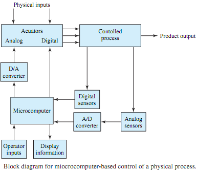
Figure shows a block diagram for microcomputer-based control of a physical process, such as a chemical plant. A slight variation of the system can be used for automotive instrumentation in which sensors furnish various signals for speed, fuel reserve, battery voltage, oil pressure, engine temperature, and so on. The data are presented to the driver in one or more displays on the dashboard. In a physical process on the other hand, based on the display information, an operator can assess and direct the operation of the control process through a keyboard or other input devices to the microcomputer.

Various physical inputs, such as power and materials, are regulated by actuators, which are in turn controlled by the microcomputer. Electric signals related to the controlled-process parameters, such as pressure and temperature, are produced by various sensors, which in turn feed the information to the microcomputer. Actuators and sensors may be either analog or digital. Digital-to-analog (D/A) converters are used to convert the digital signals to analog form so as to suit the analog actuators, where as analog-to-digital (A/D) converters are employed to convert the analog sensor signals to digital form so as to suit the microcomputer.

1746_Digital Process Control.png

One can think of so many systems in daily practice controlled or monitored by microcomputers. Some examples include monitoring patients in intensive cardiac-care units of hospitals, nuclear-reactor controls, traffic signals, aircraft and automobile instrumentation, chemical plants, and various manufacturing processes.


Related Discussions:- Explain working of digital process control

Factors affecting frequency response of an amplifier, Q. What is their rela...

Q. What is their relation with gain? What are the factors affecting frequency response of an amplifier? Some amplifiers should be "flat" across a band of frequencies. In other

Stator voltage control methods - motor control , Stator Voltage Control Met...

Stator Voltage Control Methods By  controlling  the applied voltage  the speed  of an  induction motor  can be  controlled. Since  the output  torque of 3-? induction motor  i

Torque required to turn a self excited generator, Work must be done against...

Work must be done against the electromagnetic torque in order to generate the voltage (and current) supplied to the electrical load connected to the generator. Therefore energy con

Combinational logic circuit , Design a combinational logic circuit to conve...

Design a combinational logic circuit to convert XS3BCD code in to the  standard 8421 BCD code.

Sketch the resulting transfer curves, Q. Consider the MOSFET circuit with v...

Q. Consider the MOSFET circuit with variable voltage, with RD = 2k and VDD = 12 V. The static characteristics of the n-channel enhancement MOSFET are given in Figure. (a) Drawt

Consequent effects on the real and reactive power losses, Q. Consider an up...

Q. Consider an upgrade of a three-phase transmission system in which the operating line-to-line voltage is doubled, and the phase or line currents are reduced to one-half the previ

Allocative efficiency, Allocative Efficiency: A neoclassical concept refer...

Allocative Efficiency: A neoclassical concept referring to allocation of productive resources (labour, capital, etc.) in a manner that best maximizes well-being (or 'utility') of

Calculate the rated load current of machine, A 500 MVA, 33kv, three phase s...

A 500 MVA, 33kv, three phase steam turbine generator has a synchronous reactance of 1.6 p.u. It delivers a rated output at 0.8 power factor lagging. Calculate (a) The synchronou

Find the truth table and the type of gate, Q. The DeMorgan's theorems sugge...

Q. The DeMorgan's theorems suggest that the basic logic operations can be realized by use of inverters and NAND gates only. For the circuits shown in Figure,  find the truth table,

\, Refer to Figure 100. Assume MKS units. Given: R1= 4, R2=14, R3= 9, I4...

Refer to Figure 100. Assume MKS units. Given: R1= 4, R2=14, R3= 9, I4= 8, I5= 7. Determine: Ieq, Req, and V3.

Write Your Message!

Captcha
Free Assignment Quote

Assured A++ Grade

Get guaranteed satisfaction & time on delivery in every assignment order you paid with us! We ensure premium quality solution document along with free turntin report!

All rights reserved! Copyrights ©2019-2020 ExpertsMind IT Educational Pvt Ltd