Explain topology method used in LAN technology in detail.
LAN Topologies: Network topology is a physical schematic that shows interconnection of the various users. There are four fundamental topologies as follows:
(i) Direct Connection or one to all topology
(ii) Star topology
(iii) Bus Topology
(iv) Ring topology
(i) Direct connection or one to one topology: In this topology, there is a path among every node and each other node. The number of paths needed is defined by the equation P = (n2-n)/2, here n is number of nodes and P is here total number of paths. Therefore number of paths rises considerably as the number of nodes raises. Each node should be physically capable to connect to paths to every other node therefore a very large connector and connected interface support circuitry is required at each node. Adding a new node needs main rewiring and affects the software which manages communications for the system.
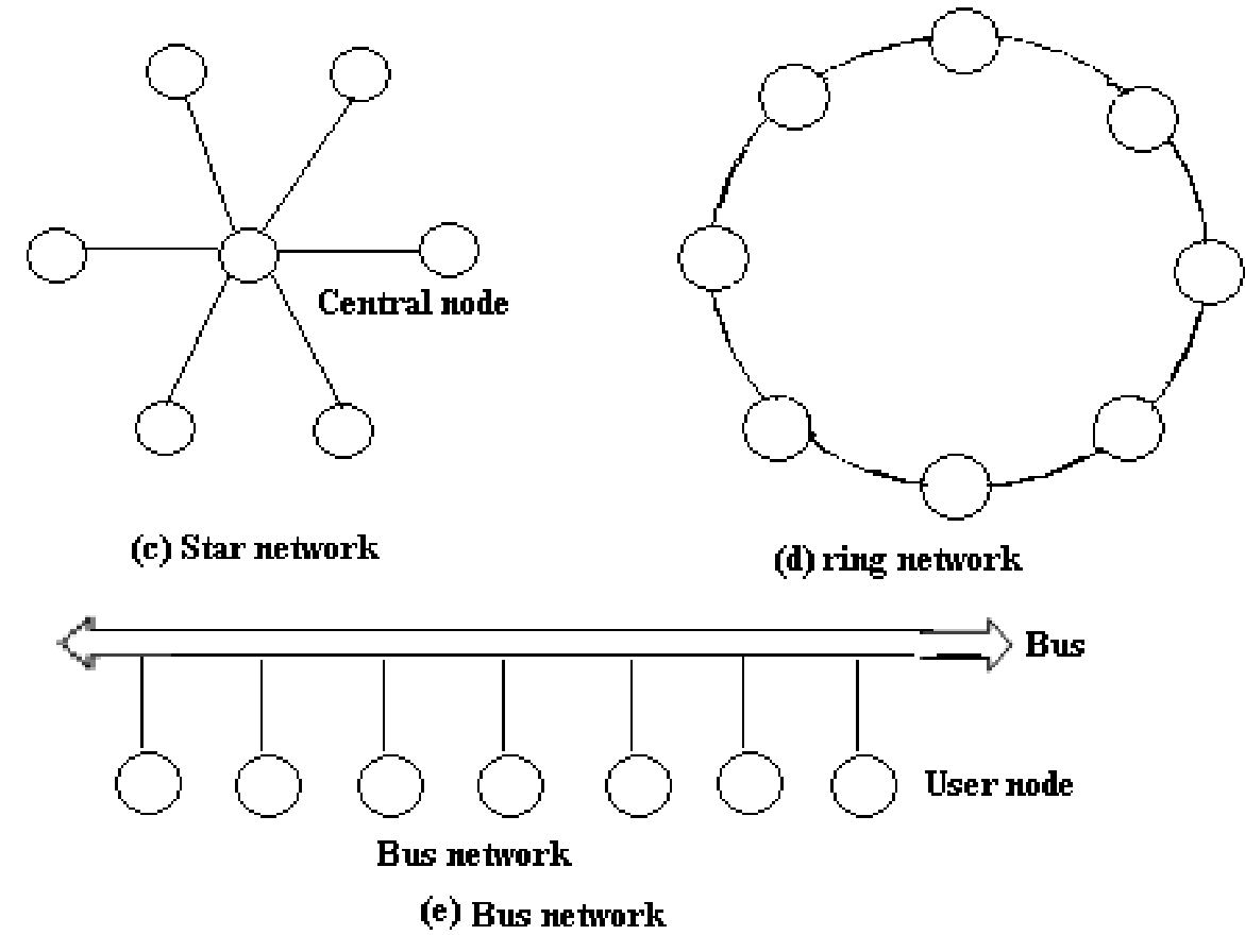
(ii) Star Topology: In this topology, all user nodes are associated to central node point which interconnects all the individual user nodes and links. Data flows from one node, by the star centre to the needed receiving node. The Central node is as a large switch that routes the data from the input line to the output line. Advanced central nodes can contain multiple switching paths; therefore several paths exist at similar time. This topology is utilized in a telephone system central office. In addition of a new user node needs running only a single link from the star centre to the user without disturbing any other node.
(iii)Bus Topology: The Bus topology shares a single link or path way in between all users. This common single path way is termed as bus. In Bus topology, the link serves as a high way for all data signals, and users connect upon to the bus at their node location. In the bus configurations, network control is not centralized to a specific node. Now control is distributed between all nodes associated to the LAN. Data transmission on a bus network is generally in the form of small packets having user addresses and data. While one node/user needs to transmit data to other station, this monitors the bus to find out if it is currently being used. When no other nodes/users are communicating over the network, the monitoring node/user can begin to transmit its data. Each node should monitor all transmission on the network and find out that are intended for them.
(iv) Ring Topology: In this topology, all user nodes are associated with the physical path acting as links of a chain and the last user node is associated back to the first node. A signal going on to the next node should be processed by the first node that then passes this through to the next node. By adding a new user needs breaking the ring temporarily, inserting the new node and then re-establishing the total ring path.

FIG - Networks Topologies