With relevant diagram explain the working of master-slave JK flip flop.
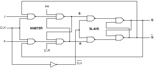
Ans. Master-Slave J-K FLIP-FLOP: A cascade of two S-R FLIP-FLOPS is a master-slave J-K FLIP-FLOP. One of them is termed as Master and the other one is slave. Fig.(a) demonstrates the logic circuit. The master is positively clocked. Because of the presence of inverter, here the slave is negatively clocked. It means that when clock is high, the slave is inactive and the master is active.
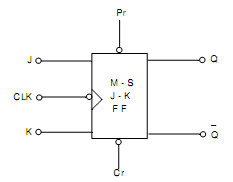
While the clock is low, the slave is active and the master is inactive. Fig.(b) demonstrates the symbol. It is a level clocked Flip-Flop. As clock is high, any changes there in J and K inputs can influence S and R outputs. Thus, J and K are kept constant throughout positive half of clock. As clock is low, the master is inactive and also J and K inputs can be permitted to be changed. The dissimilar conditions are Set, Reset and Toggle. The race condition is ignored due to feedback from slave to master and the slave being inactive throughout positive half of clock.
(i) SET State: Suppose that Q is low and Q‾ is high. For high J, low K and high CLK, the Master goes to SET state providing High S and Low R. As Slave is inactive, Q and Q‾ do not change. While CLK is Low, the Slave becomes to Set state providing High Q and low Q‾.
(ii) RESET State: At the ending of Set State Q is High and Q‾ low. Here if J is low, K is high and CLK is high, the Master Resets providing Low S and High R. Q and Q‾ do not change since Slave is inactive. While CLK becomes Low, the Slave changes active and resets providing Low Q and High Q‾.
(iii) Toggle State: The Slave copies the Master, if both J and K are high. While CLK is High, the Master toggles once. After that the Slave toggles once when CLK is low. If the Master toggles in Set state, the slave copies the Master and toggles in Set state. If the Master toggles in Reset state, the slave again copies the Master and toggles in Reset state. Because the second FLIP-FLOP only follows the first one, this is termed to as the slave and the first one as the master. Therefore, this configuration is termed to as master- slave (M-S) FLIP-FLOP.
JK Master Slave Flip-Flop Truth Table shows that a Low PR and Low CLR can cause race condition. Therefore, PR and CLR are kept High when inactive. To clear, we make CLR Low and to preset we make PR Low. In both cases we change them to High while the system is to be run.
Low J and Low K make inactive state irrespective of clock input. the next clock pulse resets the Flip-Flop, if K goes High. If J goes High through itself, the subsequent clock pulse sets the Flip-Flop. While both J and K are High, all clock pulse generates one toggle.

Fig.(a) Logic Diagram of Master-Slave J-K FLIP-FLOP

Fig.(b) Logic Symbol of Master-Slave J-K FLIP-FLOP
|
|
|
Inputs
|
|
|
Output
|
|
PR
|
CLR
|
CLK
|
J
|
K
|
Q
|
|
0
|
0
|
X
|
X
|
X
|
Race Condition
|
|
0
|
1
|
X
|
X
|
X
|
1
|
|
1
|
0
|
X
|
X
|
X
|
0
|
|
1
|
1
|
X
|
0
|
0
|
No change
|
|
1
|
1
|
|
|
|
0
|
1
|
0
|
|
|
|
1
|
1
|
|
|
|
1
|
0
|
1
|
|
1
|
1
|
|
1
|
1
|
Toggle
|
|
|
|
|
|
|
Truth Table of JK Master-Slave Flip-Flop