Explain the fixed logic versus programmable logic, Computer Engineering

Assignment Help:

Explain the Fixed Logic Versus Programmable Logic?

The Logic devices can be classified into two broad categories - fixed and programmable. The same as the name suggests, the circuits in a fixed logic device are permanent, they perform one function or set of functions - once manufactured, they cannot be changed. On the other side, programmable logic devices (PLDs) are standard, off-the-shelf parts that offer customers a wide range of logic capacity, features, speed, and voltage characteristics - and these devices can be changed at any time to perform any number of functions.

With fixed logic devices, the time necessary to go from design, to prototypes, to a final manufacturing run can take from several months to more than a year, depending on the complexity of the device. And if the device doesn't work correctly or if the requirements change a new design must be developed.

1574_Fixed Logic Versus Programmable Logic.png

With programmable logic devices, designers use inexpensive software tools to quickly simulate, develop, and test their designs then, a design can be quickly programmed into a device, and immediately tested in a live circuit. The PLD that is used for this prototyping is the accurate same PLD that will be used in the final production of a piece of end equipment, such as a network router, a DSL modem, a DVD player, or an automotive navigation system. Thus the development cost can be reduced.

Another major benefit of using PLDs is that during the design phase customers can change the circuitry as often as they want until the design operates to their satisfaction. That's for the reason that PLDs are based on re-writable memory technology - to change the design, the device is simply reprogrammed. Formerly the design is final customers can go into immediate production by simply programming as many PLDs as they need with the final software design file.

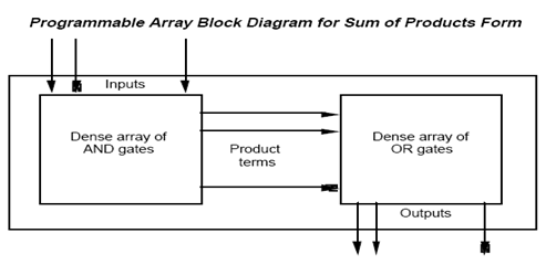
PLD is an integrated circuit with internal logic gate that are connected by electronics fuses. Programming signifies blowing of fuses.


Related Discussions:- Explain the fixed logic versus programmable logic

Define refresh circuits, Define Refresh Circuits? It is a circuit which...

Define Refresh Circuits? It is a circuit which make sure that the contents of a DRAM are maintained when every row of cells are accessed periodically.

Ground substitution, Ground substitution: Here the act of performing a...

Ground substitution: Here the act of performing an instantiation is a function like there is only one possible outcome means we can write it as a function. And the notation Su

Options with dir in dos, Q. Options with DIR in DOS? You can use a numb...

Q. Options with DIR in DOS? You can use a number of options with DIR. To get the list of files from any other drive, denote the drive name followed by ':' with DIR. For exam

State the data flow diagramming conpects, State the data flow diagramming c...

State the data flow diagramming conpects The approach to data flow diagramming is as follows: Create a data flow diagram for each of major outputs of system Work ba

History, #what is the history of computer science

#what is the history of computer science

Hypothetical reliable data transfer protocol, the c code for hypothetical r...

the c code for hypothetical reliable data transfer protocol

What is functional modelling, What is  Functional Modelling  We know ...

What is  Functional Modelling  We know that Data flow modelling is an ordinary technique used for analysis of a problem in software engineering. It is very useful for analyzi

Define edge-triggered s-r flip-flop, Define Edge-triggered S-R flip-flop ...

Define Edge-triggered S-R flip-flop Basic Symbol small triangle, called the dynamic input indicator, is used to identify an edge-triggered flip-flop. Truth Table.

What is nv-ram, Nonvolatile Read Write Memory, also kown as Flash memory. I...

Nonvolatile Read Write Memory, also kown as Flash memory. It is also called as shadow RAM.

Determine the o/p when i/p A=11001 is applied to a NOT gate, When an input ...

When an input signal A=11001 is applied to a NOT gate serially, its output signal is ? Ans. First input applied will be LSB 00110, as A=11001 is serially applied to a NOT gate

Write Your Message!

Captcha
Free Assignment Quote

Assured A++ Grade

Get guaranteed satisfaction & time on delivery in every assignment order you paid with us! We ensure premium quality solution document along with free turntin report!

All rights reserved! Copyrights ©2019-2020 ExpertsMind IT Educational Pvt Ltd