Explain the different types of multivibrators, Electrical Engineering

Assignment Help:

Explain the different types of multivibrators ?

Multivibrator is basically  a two-stage amplifier with output of one supplied back to the input of the other .

852_Explain the different types of multivibrators.png

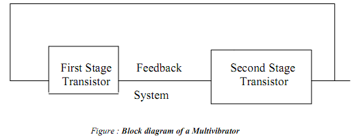
Multivibrator is a switching circuit and may be defined as an electronic circuit that generates non-sinusoidal waves, such as rectangular waves, saw tooth waves, square waves etc. Multivibrators are capable of storing binary numbers, counting pulses, synchronsing arithmetic operations and performing other, essential functions in digital systems. In a multivibrator, each amplifier stage supplies feedback to the other stage in such a way that one transistor is driven to saturation and the other to cut-off or vice-versa. This is termed as the state of the multivibrator. The condition in which the multivibrator may remain indefinitely until the circuit is triggered by some external signal is termed as the stable state.

There are only two possible states of a multivibrator are as follows:

  First state: Transistor T1 'on' and transistor T2 'off'

  Second state: Transistor T1 'off' and transistor T2 'on '

Depending upon the type of coupling network employed, the multivibrators are classified into the following three categories.

1. Astable or free-running multivibrator.

2. Monostable or single-shot multivibrator.

3. Bistable or flip-flop multivibrator.

The first one is the non-driven type whereas the other two are the driven type (also called triggered oscillators).

Multivibrators are used for various purposes such as generation of non-sinusoidal waveforms ( square, rectangular, sawtooth etc.) and pulses occurring  periodically, frequency division, synchronized generation of pulses and extended waveforms, generation of time delays, storage of binary bit of information etc.


Related Discussions:- Explain the different types of multivibrators

Can you explain working principle of tl - ac alternator, Can you explain wo...

Can you explain working principle of TL/AC alternator? Ans . The core of the stator which is completely induced by the field coils, will get a residual magnetism if excited b

Thevenin equivalent circuit, The circuit below will be most efficiently ana...

The circuit below will be most efficiently analyzed by obtaining the Thevenin equivalent circuit for the circuit to the left of the points (a-b) on the schematic. The capacitor is

Power distribution, Power Distribution You will study about the legisl...

Power Distribution You will study about the legislative measures that have been taken by our government to address these challenges. In particular, we discuss the Energy Conse

Explain the electrical contact materials with examples, Explain the electri...

Explain the electrical contact materials with examples. Electrical contact materials: A number of elements in their pure form as copper, nickel, palladium, molybdenum, platin

#titl4 bit binary addere.., Ask question #Madvantages of 4 bit binary adder...

Ask question #Madvantages of 4 bit binary adder inimum 100 words accepted#

Calculation of aggregate technical and commercial loss, Calculation of Aggr...

Calculation of Aggregate Technical and Commercial Loss The concept of AT&C loss was introduced within 2001-02. The AT&C losses are presently in the range of 18% to 62% in seve

Help assignments, A three-phase transposed line is composed of one conducto...

A three-phase transposed line is composed of one conductor per phase with flat horizontal spacing of 11 m as shown in Figure 1(a). The conductors have a diameter of 3.625 cm and a

RLC circuit, A series RLC circuit consisting of resistor of 200 ohms, an in...

A series RLC circuit consisting of resistor of 200 ohms, an inductor of 0.214H and a capacitor of unknown value. When this circuit is energized by 240 i) value of capacitor ii) vol

Find the resonant frequency, Find the resonant frequency: Find the res...

Find the resonant frequency: Find the resonant frequency ω0 (or f0) for the given series RLC circuit v = Vm sin ωt = 50 sin ωt Figure Also determine the expre

Write Your Message!

Captcha
Free Assignment Quote

Assured A++ Grade

Get guaranteed satisfaction & time on delivery in every assignment order you paid with us! We ensure premium quality solution document along with free turntin report!

All rights reserved! Copyrights ©2019-2020 ExpertsMind IT Educational Pvt Ltd