Explain synchronisation and parallel operation, Electrical Engineering

Assignment Help:

Explain Synchronisation and Parallel Operation

Generation, transmission and distribution of electric power have to be conducted in an efficient and reliable way at a reasonable cost with the least amount of interruptions. Consequently, in a large power system many synchronous generators are connected in parallel to a common line known as an infinite bus of fixed voltage and frequency, and pre-determined phase sequence. A number of safety requirements need to be satisfied prior to connecting a generator to the infinite bus (this is called a synchronising procedure):

2448_Explain Synchronisation and Parallel Operation.png

(1) The operating frequency,

(2) The line voltage and

(3) The phase sequence must all be the same as those for an infinite bus.

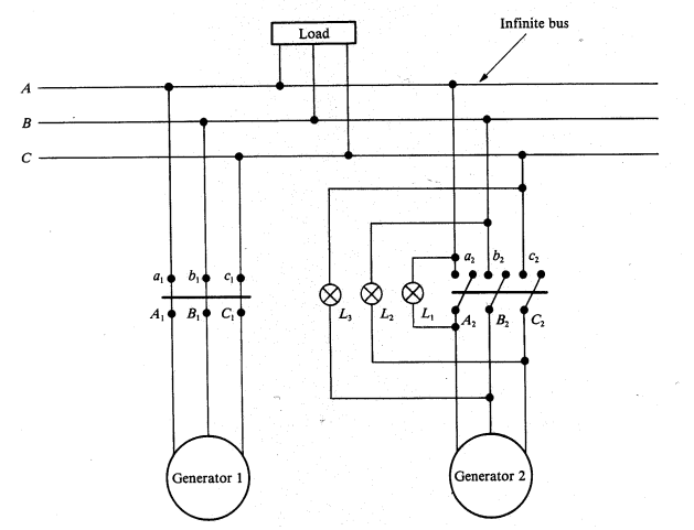
To meet an increased load demand, let us, for instance, bring a second generator into service as shown in Figure. The necessary synchronisation procedure consists of the following major steps. The speed of the incoming generator is adjusted to obtain the frequency of the induced voltage equal to that of the infinite bus. Now that the frequency match is achieved the field current can be raised to a level at which the induced voltage of the second generator is identical to the bus voltage. In order to verify the phase sequence, three lamps are connected asymmetrically as illustrated in the figure. When the phase sequence is correct, the lamp LI will be dark, while the other two lamps will glow brightly. If the phase sequence is not proper, all the lamps will glow or become dark simultaneously. When all the above conditions are met, the second generator can be safely connected to the infinite bus by closing the appropriate circuit breaker.

In addition to the lamps to check the conditions for synchronism, an electronic device (often computer controlled) called a synchroscope is also used to perform a precise switching when the above criteria are fulfilled. It provides the information on the incoming generator as to whether it is running at a lower or higher speed. At a proper speed and a correct phase sequence, the synchroscope indicates zero when the synchronising switch must be closed to connect the second generator on line. At this moment, it is neither receiving nor delivering any power. This is referred to as the floating stage of the generator. If we now increase the field current, the second generator will produce reactive power and help improve voltage regulation. Else, if an attempt is made to increase the rotor speed, the torque developed will increase and the second generator will begin to supply active power to the load.


Related Discussions:- Explain synchronisation and parallel operation

Switching characteristics during turn off, Switching Characteristics During...

Switching Characteristics During Turn off The techniques  used for turning off a thyristor is known  as  commutation techniques. A  thyristor can be can be  turn off by reducin

Find current in bjt, Q. A BJT is biased by the method shown in Figure. If V...

Q. A BJT is biased by the method shown in Figure. If V BEQ = 0.7V, β = 100, V CEQ = 10 V, and I CQ = 5 mA, find I 1 , I 2 , and IEQ.

Network topology, LAN topologies: Network topology is a physical schematic...

LAN topologies: Network topology is a physical schematic that demonstrates interconnection of the many users. There are four fundamental topologies as under: (i) Direct Connect

Switching characteristics during turn on , Switching characteristics during...

Switching characteristics during turn on A positive  gate  pulse  between  gate and  cathodeis sufficient to turn  on a thyrisotr. In  this period  thyristor  changes its stat

Explain stages of attending to rail fracture, Q. Explain stages of attendin...

Q. Explain stages of attending to Rail fracture? Various stages of attending to Rail fracture / weld failure in a L.W.R. track in field - Equipment required - i) Special

V-i characteristics - power semiconductor devices, V- I Characteristics ...

V- I Characteristics When the peak  value of  applied  voltage is less than the break over   voltage  of triac  and no signal  is applied to the triac  it will block  both  pos

Design an appropriate system, From a source with P in = 2.4 mW, we want to...

From a source with P in = 2.4 mW, we want to get P out = 60 mW at a distance l = 20 km from the source. α for the transmission line is given to be 2.3 dB/km. The available amplif

Show procedure of divide the decimal number by 2, Q. Show procedure of divi...

Q. Show procedure of divide the decimal number by 2? For this procedure (method), divide the decimal number by 2, if the remainder is 0, on the side write down a 0. If the rema

Determine the current in the diode, Q. Consider the circuit shown in Figure...

Q. Consider the circuit shown in Figure. Determine the current in the diode by assuming: (a) The diode is ideal. (b) The diode is to be represented by the model of Figure 7.2

Write Your Message!

Captcha
Free Assignment Quote

Assured A++ Grade

Get guaranteed satisfaction & time on delivery in every assignment order you paid with us! We ensure premium quality solution document along with free turntin report!

All rights reserved! Copyrights ©2019-2020 ExpertsMind IT Educational Pvt Ltd