Explain mesh - current method, Electrical Engineering

Assignment Help:

Q. Explain Mesh - Current Method?

This complements the nodal-voltage method of circuit analysis. A set of independent mesh-current variables that implicitly satisfy the KCL equations is selected in order to formulate circuit equations in this mesh analysis. An elementary loop,ora mesh, is easily identified as one of the "window panes" of the whole circuit. However, it must be noted that not all circuits can be laid out to contain only meshes as in the case of planar networks. Those which cannot are called nonplanar circuits, for which the mesh analysis cannot be applied, but the nodal analysis can be employed.

A mesh current is a fictitious current, which is defined as the one circulating around a mesh of the circuit in a certain direction. While the direction is quite arbitrary, a clockwise direction is traditionally chosen. Branch currents can be found in terms of mesh currents, whose solution is obtained from the independent simultaneous equations. The number of necessary equations in the mesh-analysis method is equal to the number of independent loops or meshes.

812_Mesh - Current Method1.png

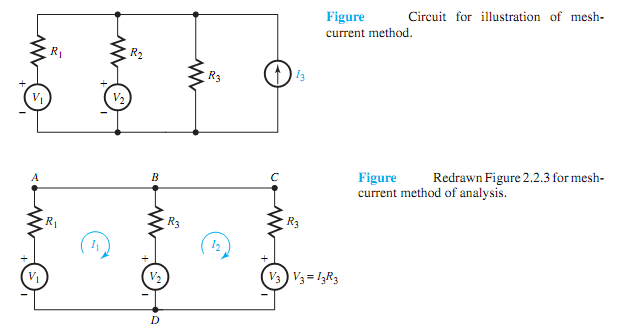
All current sourceswith shunt conductanceswill be replaced by their corresponding Thévenin equivalents consisting of voltage sources with series resistances. Let us illustrate the method by considering a simple, but typical, example, as shown in Figure (a).

Replacing the current sourcewith shunt resistance by the Thévenin equivalent, Figure (a) is redrawn as Figure (b), in which one can identify two elementary loops, or independent meshes.

By assigning loop or mesh-current variables I1 and I2, as shown in Figure (b) , both in the clockwise direction, one can write the KVL equations for the two closed paths (loops) ABDA and BCDB,

1575_Mesh - Current Method.png


Related Discussions:- Explain mesh - current method

Use ideal op-amp technique to find voltage at point, Q. In the circuit show...

Q. In the circuit shown in Figure, use the ideal op-amp technique to find: (a) v o as a function of v i . (b) The voltage at A.

Analog-to-digital converters, Analog-to-Digital (A/D) Converters An A/D...

Analog-to-Digital (A/D) Converters An A/D converter converts analog input signals into digital output data in many areas such as process control, aircraft control, and telemetr

For configurations of the coupled coils obtain the voltage, Q. For the conf...

Q. For the configurations of the coupled coils shown in Figure, obtain the voltage equations for v 1 and v 2 .

Explain working of digital-to-analog converters, Q. Explain working of Digi...

Q. Explain working of Digital-to-Analog Converters? Digital-to-Analog (D/A) Converters For the results of digital computations to be used in the analog world, it becomes n

Performance equations of three phase induction motor , Performance Equation...

Performance Equations of Three Phase Induction Motor When balanced 3-? voltages are applied to the  stator  winding  a rotating magnetic field  of constant amplitude is produc

Determine the ranges of values of the gain constant, A unity negative feedb...

A unity negative feedback control system has an open loop transfer function consisting of two poles, two zeros and a variable positive gain K. The zeros are located at -2 and -1, a

Zener Diode, A Zener diode has the specifications VZ=6.8V and PDmax.=500mW....

A Zener diode has the specifications VZ=6.8V and PDmax.=500mW. Assume RZ=0. (a) Find the maximum allowable current iZ when the Zener diode is acting as a regulator. (b) If a sing

How does expert system works, How does Expert system works? System uses...

How does Expert system works? System uses a rule base and an inference engine together to simulate human reasoning whenever analysing a problem and arriving at a conclusion. To

Operation of zener diode, Operation of Zener Diode The Zener diode's o...

Operation of Zener Diode The Zener diode's operation depends upon the heavy doping of its p-n junction permitting electrons to tunnel from the valence band of the p-type mater

Find the current and voltage at input terminals of the line, Q. A source of...

Q. A source of impedance ¯ Z S = R S = 100  has an open-circuit voltage v S (t) = 12.5 cos ωot and drives a 75- transmission line terminated with a 75- load. Find the current

Write Your Message!

Captcha
Free Assignment Quote

Assured A++ Grade

Get guaranteed satisfaction & time on delivery in every assignment order you paid with us! We ensure premium quality solution document along with free turntin report!

All rights reserved! Copyrights ©2019-2020 ExpertsMind IT Educational Pvt Ltd