Explain medium length lines, Electrical Engineering

Assignment Help:

Explain Medium length lines?

Medium length lines cover lines in the range of 50 to 150 miles (80 to 240 km). Due to the increased length of the line, the shunt capacitance of the line is significant and is included in the equivalent circuit model. Therefore, the line model may be represented by a π network, as shown in Figure.

1087_Explain Medium length lines.png

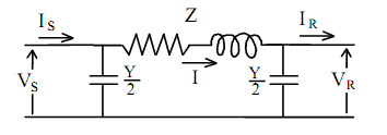
Using Kirchhoff's voltage and current laws, the π circuit gives:

VS = VR + Z I         (1)

I = IR + Y/2 VR      (2)

IS = I + Y/2 VS      (3)

To obtain VS and IS in terms of VR and IR , substitute equation (2) into (1) which gives:

VS = [(1 + ZY) / 2] VR + Z IR                                                    (4)

Substituting equations (4) and (2) into equation (3) and rearranging yields:

IS = [(1 + ZY) / 4] Y VR + [(1 + ZY) / 2] IR        (5)

Comparing equations (4) and (5) with equations gives the 2-port network constants as:

A = [(1 + ZY) / 2], B = Z

C = [(1 + ZY) / 4], D = [(1 + ZY) / 2] = A

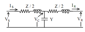
Another way of representing a medium length line is by the Τ network shown in Figure. In this case:

VS = VC + Z/2 IS                                              (6)

VC = VR + Z/2 IR   and                          (7)

IS = IR + Y VC                                                   (8)

1583_Explain Medium length lines 2.png

As for the π network, equations (6-8) may be solved and rearranged to obtain VS and IS in terms of VR and IR as:

VS = [(1 + ZY) / 2] VR + [(1 + ZY) / 4] IR                                           (9)

IS = Y VR + [(1 + ZY) / 2] IR                                                                     (10)

This gives the 2-port network constants as:

A = [(1 + ZY) / 2], B = [(1 + ZY) / 4] Z

C = Y, D = [(1 + ZY) / 2] = A


Related Discussions:- Explain medium length lines

State the function of rs1 and rs0 bits, State the function of RS1 and RS0 b...

State the function of RS1 and RS0 bits in the flag register of intel 8051 microcontroller? RS1 , RS0 - Register bank select bits RS1   RS0 BankSelection 0        0   Bank

Dc machine dynamic performance, Calculate the following for a 2 hp and a 20...

Calculate the following for a 2 hp and a 20 hp dc machine, each rated for 500 rpm. Use data from the Study Plan 1 data sheet, including "hot" armature resistance value for all cal

Bias circuit requirements, Bias circuit requirements: Signal requirem...

Bias circuit requirements: Signal requirements for Class A amplifiers The Q-point is placed thus the transistor stays in active mode (does not shift to operation in the s

Fiind the magnitudes of the line-to-line voltages, Q. A single-line diagram...

Q. A single-line diagram of a three-phase transformer bank connected to a load is given in Figure. Find the magnitudes of the line-to-line voltages, line currents, phase voltages,

Sampled-data and digital control systems, Q. Sampled-data and digital contr...

Q. Sampled-data and digital control systems? These differ fromthe continuous-data systems in that the signals at one or more points of the system are in the form of either a pu

Measure phase angle by using an oscilloscope, 1. Introduction : ...

1. Introduction : Theory:  Phase angle is defined as the number of degrees separating two sine waves of the same frequency. The Phase shift is defined as any change t

Determine the armature current and torque angle, Q. Determine the armature ...

Q. Determine the armature current and torque angle? A 1500-hp, 6600-V, six-pole, 60-Hz, three-phase, wye-connected, synchronous motor, with a synchronous reactance of 36 , neg

Write Your Message!

Captcha
Free Assignment Quote

Assured A++ Grade

Get guaranteed satisfaction & time on delivery in every assignment order you paid with us! We ensure premium quality solution document along with free turntin report!

All rights reserved! Copyrights ©2019-2020 ExpertsMind IT Educational Pvt Ltd