Q. Explain Global Positioning Systems?
Modern communication systems abound in practice: cellular phones, computer networks, television satellites, and optical links for telephone service. Communication with instruments has been made possible between our planet, the earth, and Mars.
A global positioning system (GPS) is a modern and sophisticated system in which signals are broadcast from a network of 24 satellites. A receiver, which contains a special-purpose computer to process the received signals and compare their phases, can establish its position quite accurately. Such receivers are used by flyers, boaters, and bikers. Various radio systems that utilize phase relationships among signals received from several radio transmitters have been employed in navigation, surveying, and accurate time determination. An early system of this type, known as LORAN, was developed so that the receivers could determine their latitudes and longitudes.
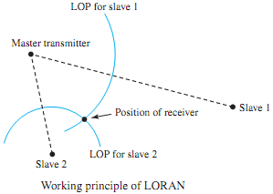
Figure illustrates in a simple way the working principle of LORAN, which consists of three transmitters (amaster and two slaves) that periodically broadcast 10-cycle pulses of 100-kHz sine waves in a precise phase relationship. The signal received from each transmitter is phase- shifted in proportion to the distance from that transmitter to the receiver. A phase reference is established at the receiver by the signal from the master transmitter; then the receiver determines the differential time delay between the master and each of the two slaves. The difference in time delay between the master and a given slave yields a line of position (LOP), as shown in Figure.
If the time delays of the signals fromthemaster and a given slave are equal (i.e., no differential delay), then the line of position is the perpendicular bisector of the line joining the master and that particular slave. On the other hand, if the time delay from the master is smaller by a certain amount, the line of position happens to be a hyperbola situated toward and near the master, as illustrated by LOP for slave 1 in Figure, and LOP for slave 2, where the time delay from slave 2 is smaller. The intersection of the LOPs for the two slaves determines the location of the receiver.
The simple concept of relative phase relationships is exploited by engineers and scientists in several systems that are beneficial to the general public. For example, remote measurements of the height of Greenland's ice cap (by using high-quality GPS receivers) are being made to assess the possible effects of global warming.