Explain fourier series, Electrical Engineering

Assignment Help:

Q. Explain Fourier Series?

The phasor method of circuit analysis can be extended (by using the principle of superposition) to find the response in linear systems due to nonsinusoidal, periodic source functions. A periodic function (t) with period T can be expressed in Fourier series,

568_Fourier Series.png


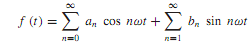
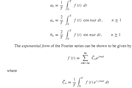
where ω = 2πf = 2π/T is the fundamental angular frequency, a0 is the average ordinate or the dc component of the wave, (a1 cos ωt + b1 sin ωt)isthe fundamental component, and (an cos nωt + bn sin nωt), for n ≥ 2, is the nth harmonic component of the function. The Fourier coefficients are evaluated as follows:

2098_Fourier Series1.png

Even though the exact representation of the nonsinusoidal, periodic wave requires an infinite number of terms in the Fourier series, a good approximation for engineering purposes can be obtained with comparatively few first terms, since the amplitude of the harmonics decreases progressively as the order of the harmonic increases.

The systemresponse is determined by the principle of superposition, and the phasor technique yields the steady-state response. Each frequency component of the response is produced by the corresponding harmonic of the excitation. The sum of these responses becomes the Fourier series of the system response. Note that while the phasor method is employed to determine each frequency component, the individual time functions must be used in forming the series for the system response. Such a method of analysis is applicable to all linear systems.


Related Discussions:- Explain fourier series

Explain ferrimagnetic magnetic materials, Explain Ferrimagnetic magnetic ma...

Explain Ferrimagnetic magnetic materials. Ferrimagnetic Materials: In such materials unequal magnetic dipoles are lined up anti-parallel to each other. And permeabilities are

Find the corresponding energy, Q. Consider a pair of coupled coils as shown...

Q. Consider a pair of coupled coils as shown in Figure of the text, with currents, voltages, and polarity dots as indicated. Show that the mutual inductance is L 12 = L 21 = M by

Analogue and digital, 1. Pattern recognition A synchronous sequential machi...

1. Pattern recognition A synchronous sequential machine is to generate 1 on output z after the next clock pulse whenever the bit sequence on input x has exactly two 0’s in the last

Determine the value of maximum power, Determine the value of maximum power:...

Determine the value of maximum power: Determine the value of load resistance, R L for which the source shall transfer the maximum power. Also determine the value of maximum p

Explain relative data addressing mode, Explain relative data addressing mod...

Explain relative data addressing mode (with examples) available in microprocessors. Relative Mode: Operand supplied is an offset, not the actual address. Added the con

Show frequency response using pspice and probe, Q. Show Frequency response ...

Q. Show Frequency response using pspice and probe? PSpice is capable of performing transient circuit analysis, for which the request is given by the following statement: • T

Testing of ct operated meters, Testing of CT Operated Meters The subse...

Testing of CT Operated Meters The subsequent tests should be carried out for CT operated meters: i) Ratio test through primary injection kit, ii) Polarity test, iii)

the battery and capacitor combination for power backup, Why do wenot see t...

Why do wenot see the battery and capacitor combination for power backup? Ans) There are "super capacitors" that are used for power backup - they are well-organized for short-te

Write Your Message!

Captcha
Free Assignment Quote

Assured A++ Grade

Get guaranteed satisfaction & time on delivery in every assignment order you paid with us! We ensure premium quality solution document along with free turntin report!

All rights reserved! Copyrights ©2019-2020 ExpertsMind IT Educational Pvt Ltd