Explain Suitability of ferrites for high frequency application.
Ferrites are extensively used in micro wave equipments and in computers. Ferrites are advantageous at high frequencies due to low eddy current losses. Ferromagnetic alloys cores and metals have to be eliminated in order to decrease the losses. At high frequencies laminations should be so thin therefore both fabrication and assembly become costly processes. At such frequencies a duet core that consists of fine particles of ferromagnetic material insulated from each other may be utilized. But these have the disadvantage of diluting the ferromagnetic martial and reducing the effective relative permeability. Further disadvantage is that the flux density varies by the core because of non-uniform spacing of the particle. At certain points where there is greater concentration of particles; therefore flux density is probable to be higher entailing larger hysteresis losses.
For this purposes, Ferrites are used for the high frequency application
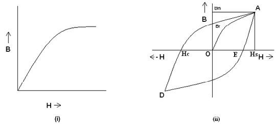
Hysterisis Loop of Magnetic Materials
A magnetic material is composed of magnetic dipoles oriented in random direction is zero. If a magnetic material is magnetized by applying a magnetizing force (i.e. MI), the magnetic dipoles begin orienting themselves towards applied magnetic force. As the magnetizing force is raised by increasing the magnetizing force, more and more of the magnetic dipoles become oriented. A stage comes while almost whole magnetic dipoles becomes oriented and as any increase in magnetizing force (MI) does not result in any increase in the dipoles getting oriented. Thus the magnetic field is established in the forward direction.
This stage of magnetization is termed as magnetic saturation as shown in figure. If the magnetizing force is slowly reduced this is found that the magnetic dipoles again get de-oriented, the rate of de-orientation now being small less than the rate of orientation at an exact magnetizing forces. Therefore the demagnetizing curve does not retrace back the magnetization curve as shown in figure (ii)
In figure (ii), OA is the magnetization curve and AB is the demagnetization curve. This may be seen that even while the magnetization force is reduced to zero, a small magnetization is left in the magnetic material. In the figure OB represents the residual magnetization. When the magnetizing force is applied now in the negative direction, a small amount of magnetizing force OC will be spent in fully de-magnetizing the material. Further increase in magnetizing force will orient the magnetic dipoles in the opposite direction therefore establishing a magnetic field into the reverse direction.
While the magnetizing force is reduced to zero and after that again increased in the forward direction therefore the magnetization curve will follow the path DEA. The whole curve ABCDEA is termed as the hysteresis loop.