Q. Explain Digital control systems?
Significant progress has been made in recent years in discrete-data and digital control systems because of the advancesmade in digital computers andmicrocomputers, as well as the advantages found in working with digital signals. Discrete-data and digital control systems differ from the continuous-data or analog systems in that the signals in one or more parts of these systems are in the form of either a pulse train or a numerical (digital) code. The terms, sampled-data systems, discrete-data systems, discrete-time systems, and digital systems have been loosely used in the control literature.However, sampled-data systems usually refer to a general class of systems whose signals are in the formof pulse data; sampled data refers to signals that are pulse-amplitude modulated, i.e., trains of pulses with signal information carried by the amplitudes. Digital control systems refers to the use of a digital computer or controller in the system; digital data usually refers to signals that are generated by digital computers or digital transducers and are thus in some kind of coded form. A practical system such as an industrial process control is generally of such complexity that it contains analog and sampled as well as digital data. Hence the term discrete-data systems is used in a broad sense to describe all systems in which some form of digital or sampled signals occur. When a microprocessor receives and outputs digital data, the system then becomes a typical discrete-data or digital control system.
Figure (a) illustrates the basic elements of a typical closed-loop control system with sampled data; Figure (b) shows the continuous-data input e(t) to the sampler, whereas Figure (c) depicts the discrete-data output e* (t) of the sampler. A continuous input signal r(t) is applied to the system. The continuous error signal is sampled by a sampling device, the sampler, and the output of the sampler is a sequence of pulses. The pulse train may be periodic or aperiodic, with no information transmitted between two consecutive pulses. The sampler in the present case is assumed to have a uniform sampling rate, even though the rate may not be uniform in some other cases. The magnitudes of the pulses at the sampling instants represent the values of the input signal e(t) at the corresponding instants. Sampling schemes, in general, may have many variations: periodic, cyclic-rate, multirate, random, and pulse-width modulated
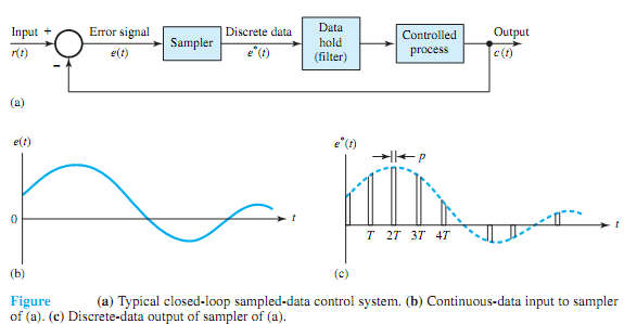
samplings. Incorporating sampling into a control system has several advantages, including that of time sharing of expensive equipment among various control channels.