Through two block diagrams explain the difference between Space division and time division switching.
Space and Time Switching:
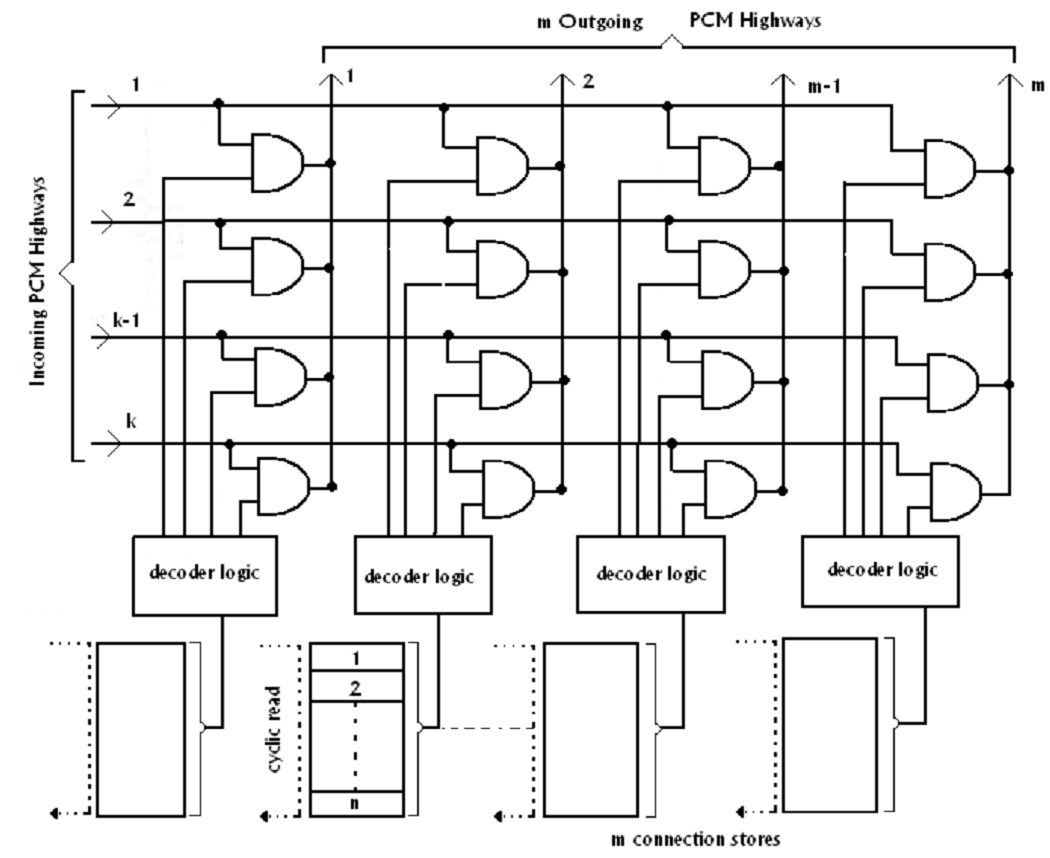
Space Switches: Connections can be made in between outgoing and incoming PCM highways by a cross point matrix of the form demonstrated in figure. However, various channels of an incoming PCM frame may require to be switched by various cross points in order to reach various destinations. Therefore, the cross point is a two-input AND gate. One input is linked to the incoming PCM highway and another to a connection store which produce a pulse at the needed instant. A group of cross points gates can be implemented like an integrated circuit, for illustration using a multiplexer chip.

FIG - Space Switch.
Figure demonstrates a space switch with k incoming and m outgoing PCM highways, all carrying n channels. The connections store for every column of cross points is a memory along with an address location for every time-slot that stores the number of the cross points to be operated in which time slot. This number is written in the address by the controlling processor so as to setup the connection. The numbers are read out cyclically, into synchronism along with the incoming PCM frame. In every time slot, the number stored at the equivalent store address is read out and decoding logic converts it in a pulse or a single lead to function the relevant cross point.
Because a cross point can make a diverse connection in each of the n time-slots, this is corresponding to n cross points in a space division network. The total space switch is therefore equivalent to n separate k x m switches in a space division switching network.
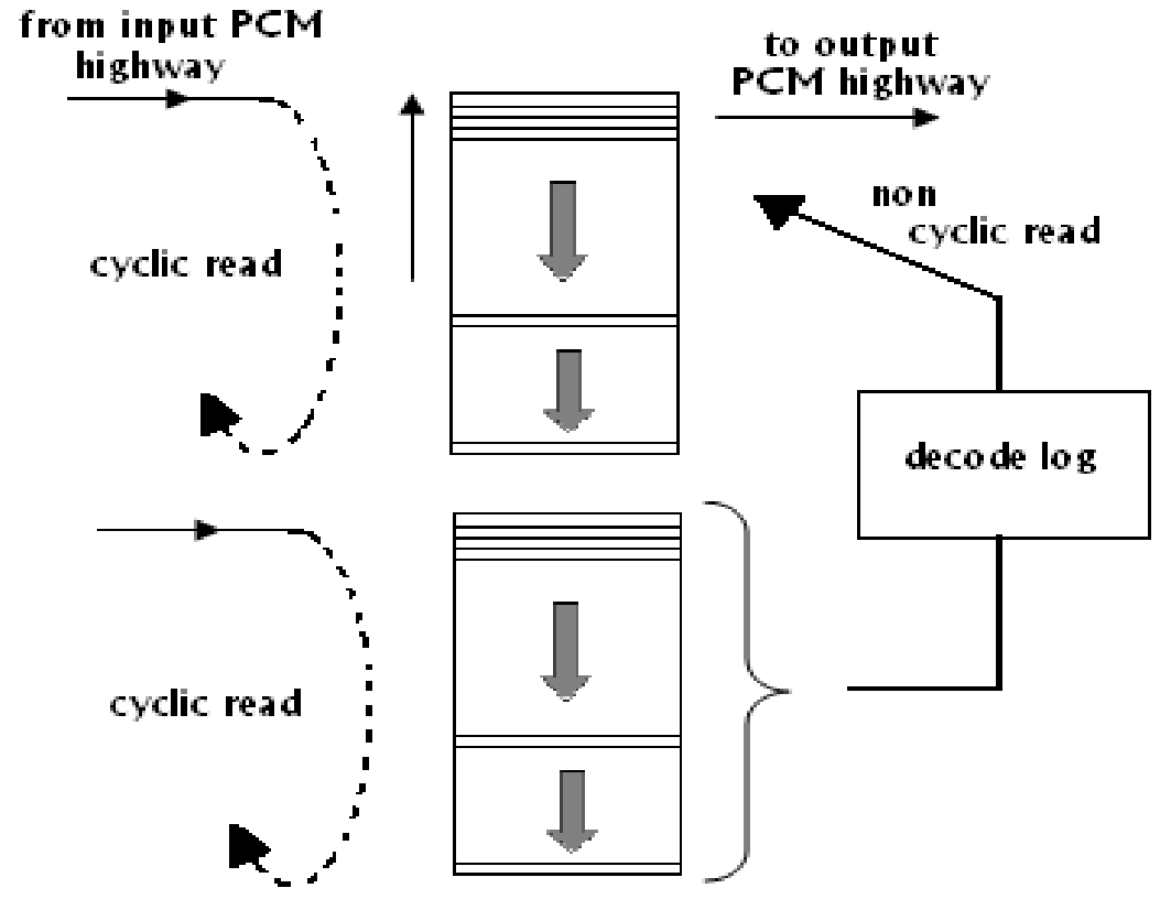
Time Switches: The principle of a time switch is demonstrated in figure. This connects an incoming n channel PCM highway to an outgoing n channel PCM highway. As any incoming channel can be connected to one outgoing channel, this is corresponding to space division cross point matrix along with n incoming and n outgoing trunks, as demonstrated in figure. Time-slot interchange is carried out through two stores, each containing a storage address for each channel of the PCM frame. The speech store consists of each data of the incoming time-slots (that is its speech sample) at a matching address. All address of the connection store corresponds to a time slot upon the outgoing highway. This contains the number of the time-slot on the incoming highways that sample is to be transmitted in which outgoing time-slots. Information is read in the speech store cyclically in synchronism with the incoming PCM systems; however, random access read out is utilized .The connection store has cyclic read out, although writing in is non cyclic. To set up a connection, the number (X of the time-slot of an incoming channel is written in the connection store at the address equivalent to the selected outgoing channel (Y ).Throughout each cyclic scan of the speech store ,the incoming PCM sample from channel X is written in address X. Throughout each cyclic scan of the connection store, the number X is read out at the starting of time-slot Y. It is decoded to select address X of the speech store, which contents are read out and sent over the outgoing highway.

FIG - Time Switch