Explain basic working of ideal operational amplifier, Electrical Engineering

Assignment Help:

Q. Explain basic working of Ideal operational amplifier?

The operational amplifier, known also as op amp, consists of several transistors, diodes, capacitors, and resistors. It is available in integrated-circuit form for less than one U.S. dollar. Being inexpensive, compact, and versatile, operational amplifiers are used in a variety of simple circuits.

Op-amp circuits, as we will see later, usually contain negative feedback. Op-amp circuits themselves can be regarded as building blocks. These blocks are characterized by their input resistance, output resistance, and open-circuit voltage amplification. The symbol for the op amp is shown in Figure. Two terminals labeled + and - are available for inputs. The voltages of these terminals are labeled with respect to the common terminal,

1801_Explain basic working of Ideal operational amplifier.png

1326_Explain basic working of Ideal operational amplifier1.png

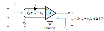
denoted by a ground symbol. The output voltage is related to the difference between the two input voltages as

vo = A(vp - vn)

where A is the open-loop voltage gain. Thus, the op amp is basically a form of differential amplifier, in which the difference vp - vn is amplified. For an output voltage on the order of 12 V, the difference voltage vd is on the order of 0.12 mV, or 120 µV. The input impedance Zi is on the order of 1 M, while the output impedance Zo is on the order of 100  to 1k.


Related Discussions:- Explain basic working of ideal operational amplifier

Determine modulation index, Q. If the output signal fromanAMmodulator is gi...

Q. If the output signal fromanAMmodulator is given by u(t) = 5 cos 1800 πt + 20 cos 2000 πt + 5 cos 2200 πt , determine: (a) The modulating signal m(t) and carrier c(t). (b)

Breifly explain abrasive jet machining, Breifly explain abrasive jet machin...

Breifly explain abrasive jet machining in Briefly explain the following key terms in electrochemical machining (a) Electrolytes (b) ECM tooling techniques with suitable ex

Evaluate currents in the circuits, Evaluate currents in the circuits: ...

Evaluate currents in the circuits: Determine currents I 1 and I 2 in the given circuits by applying KVL. Solution We apply KVL for first loop : 10 = 1 I 1   + 1 (

Feedback amplifier, explain working pricipal of nagative resistance oscilla...

explain working pricipal of nagative resistance oscillator

Design a calculator with multi functions, Aims More practice using d...

Aims More practice using data movement and control flow statements. Understand techniques to interface microprocessors with external switch-based hardware. Write P

Bias circuit requirements, Bias circuit requirements: Signal requirem...

Bias circuit requirements: Signal requirements for Class A amplifiers The Q-point is placed thus the transistor stays in active mode (does not shift to operation in the s

Emi, applications of heterodyne wave analyzer

applications of heterodyne wave analyzer

History - field-effect transistor, History - Field-Effect Transistor: ...

History - Field-Effect Transistor: The principle of field-effect transistors was very first patented by Julius Edgar Lilienfeld in the year 1925 and by Oskar Heil in the year

Shunt dc motor, Shunt DC motor In this arrangement, the armature and f...

Shunt DC motor In this arrangement, the armature and field coils are connected in parallel (the motor is called 'shunt connected').     Analysis With refere

Write Your Message!

Captcha
Free Assignment Quote

Assured A++ Grade

Get guaranteed satisfaction & time on delivery in every assignment order you paid with us! We ensure premium quality solution document along with free turntin report!

All rights reserved! Copyrights ©2019-2020 ExpertsMind IT Educational Pvt Ltd