Q. Explain about Common Control Switching System?
Common Control Switching System: A functional block diagram of a common control switching system is displayed in Figure. Control functions in a switching system may be placed under four wide categories:
(a) Event monitoring.
(b) Call processing.
(c) Charging.
(d) Operation and maintenance
Events occurring outside the exchange at line units, trunk junctions and inter exchange signalling sender/receiver units are all monitored by control subsystem. Typical events involve all request and call release signals at the line units. Occurrences of the events are signalled by operating relays that initiate control action. Control subsystem may operate relays in the junctions, senders/receivers and line units and hence command these units to perform certain functions. Events monitoring may be distributed. For illustration, line units themselves can initiate control actions on the occurrence of certain line events.
When a subscriber goes off-hook, event is sensed, calling location is determined and market for dial tone and register finder is activated to seize a free register. Identity of calling line is used to conclude the line category and class of service to which the subscriber belongs. A register appropriate to line category is chosen, which then transmits out the dial tone to subscriber, in readiness to receive dialling information. The instant the initial digits (generally 2-5) which identify exchange are received in the register, register continues to receive remaining digits.
Initial translator determines the route for call through the network and decides whether a call must be put through or not. It also figures out the charging methods and rates applicable to subscriber. Initial translation can also take into account instructions from operating personnel and information regarding the status of network.
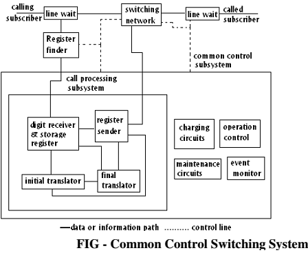
If a call is destined to a number in an exchange other than present one processing the digits, initial translator generates required routing digits and passes them on to register sender. Here digits corresponding to subscriber identification are concatenated and combined digit pattern is transmitted over the trunks to external exchange. Register sender usesproper signalling technique, depending on requirements of the destination exchange. If call is destined to a subscriber within the same exchange, digits are processed by final translator. Translation of directory number to equipment number occurs at this stage. Final translator determines the line unit to which a call should be connected and category of the called line. Category information may impact charging and connection establishment. In some practical implementations, both final and initial code translator functions are performed by a single translator. Controlling operation of the switching network isa significant function of the common control subsystem. It is done by marking the switching elements at various stages in accordance with a set of binary data defining the path and then commanding actual connection of the path. Path finding can be carried out at level of the common control unit or switching network.