Exhaust gas temperature, Physics

Assignment Help:

Exhaust gas temperature

Monitoring of the temperatures within the engine core is performed by the exhaust gas temperature system. The operating limits of the engine, and monitoring of the mechanical integrity of the turbines during operation, is vital for the continuing serviceability of the engine. 

Exhaust gas temperature, abbreviated to EGT, is only one of the terms relating to gas temperature. It can also be known as:-

• turbine gas temperature (TGT)
• jet pipe temperature (JPT)
• turbine inlet temperature (TIT)
• turbine blade temperature (TBT)
• Intermediate turbine temperature (ITT)

1886_Exhaust gas temperature.png

The EGT system consists of a series of thermocouples arranged radially in the exhaust- section of the engine. The exact location is decided by the engine manufacturer; other components within the system are:-

• a thermocouple junction box
• a balance resistor box (junction box)
• indicators on the flight deck.
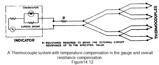
A typical system lay-out is illustrated in Fig. 14.12 .

THERMOCOUPLES

The thermocouple itself consists of two dissimilar metals joined together within the probe body. Gas inlet holes are provided in the outer casing to allow hot gases to circulate around the sensing elements. The most common types of dissimilar sensing wires used are chromel and alumel.

The probes may contain more than one thermocouple to sense the temperature at different lengths into the exhaust duct, or adjacent probes may be of different lengths. Some engines may have more than one EGT system. One for FADEC or for temperature limiting.
The junction of the two wires (within the probe) is known as the hot or measuring junction; the indicator end is known as the cold or reference junction.

The operation is fairly simple, as the thermocouple is a self-generating electrical system. Assuming that the reference end is kept at a constant temperature (flightdeck) and the hot end is subjected to high gas temperatures, then an electromotive force (emf), created by the dissimilar metals. The Seebeck effect causes the indicator to move in proportion to the difference in temperature between the two junctions.

The thermocouples are connected electrically in parallel to provide an average gas temperature. The two wires (chromel and alumel) from each thermocouple terminate at the junction box. The chromel wires are connected together to form a parallel circuit, the alumel wire is common to all thermocouples. The junction box can also be used to check the thermocouple continuity during maintenance checks.

From the junction box, the chromel and alumel wires are routed to the indicator on the flight deck.

In some installations the cold junction is not in the gauge, but is a separate thermocouple located in the intake. The benefit of this system is that when a top temperature system is used to trim the fuel control unit, the majority of the components in the temperature system are located on the engine. It will also indicate the temperature difference across the engine.


Related Discussions:- Exhaust gas temperature

The charge and discharge characteristics of lead battery, The charge and di...

The charge and discharge characteristics of lead battery: During discharge the plates are converted into lead sulphate, the water content of the electrolyte increases, the inte

Production of electricity by light, Production of electricity by light: ...

Production of electricity by light: The Photovoltaic Cell or Solar Cell. A photovoltaic cell generates an emf when light falls onto it. Several forms of photovoltaic cell exi

Electrostatics, An uncharged capacitor with a solid dielectric is connected...

An uncharged capacitor with a solid dielectric is connected to a similar air capacitor charged to a potential of V0. If the common potential after sharing of charges becomes V, the

Bulbs can fail without blowing the fuse - electricity, A holiday light stri...

A holiday light string of ten bulbs is equipped with shunts that short out the bulbs when the voltage drop increases to line voltage, which happens when a bulb burns out. Every bul

Calculate the speed and frequency of elctromagnetic wave, Imagine an elctro...

Imagine an elctromagnetic wave propagating vacuum with electric field Ex=10 2 sinπ(3x10 6 z - 9x10 14 t) V/m, E y =0, E z = 0. Calculate the speed, frequency, wavelength, initial

Tunneling and tunneling applications, Q.   What is quantum mechanical "Tunn...

Q.   What is quantum mechanical "Tunneling"? Give one example. OR What do you mean by quantum mechanical tunneling? Show that the tunneling probability is given by the

Is it probable for an electron to be moving northward, Is it probable for a...

Is it probable for an electron to be moving northward in a northward-directed electric field? Answer: The force exerted on a negatively charged particle with an electric f

Illustrate the silicon iron magnetic circuit, For the magnetic circuit show...

For the magnetic circuit shown in Figure find the current I in the coil needed to produce a flux of 0.45mWb in the air gap. The silicon iron magnetic circuit has a uniform cros

Draw a circuit diagram of a common emitter amplifier, Draw a circuit diagra...

Draw a circuit diagram of a common emitter amplifier by using n-p-n transistor. Show input and output voltages graphically. The current gain for common emitter amplifier is 59.

What is the dynamic resistance, A coil of inductance 100 mH and resistance ...

A coil of inductance 100 mH and resistance 800Ω is connected in parallel with a variable capacitor across a 12V, 5kHz supply. Determine for the condition when the supply curre

Write Your Message!

Captcha
Free Assignment Quote

Assured A++ Grade

Get guaranteed satisfaction & time on delivery in every assignment order you paid with us! We ensure premium quality solution document along with free turntin report!

All rights reserved! Copyrights ©2019-2020 ExpertsMind IT Educational Pvt Ltd